Fuel pump

Inactive Publication Date: 2005-01-04
AISAN IND CO LTD
View PDF9 Cites 1 Cited by
  • Summary
  • Abstract
  • Description
  • Claims
  • Application Information

AI Technical Summary

Benefits of technology

Under these circumstances, it has been demanded to improve the pump efficiency while ensuring a clearance sufficient to prevent the impeller outer peripheral surface and the pump casing inner peripheral surface from contacting each other even if the rotation center of the impeller is displaced as a result of wear of the bearings.
The fuel pump according to the present invention enables the pump efficiency to be improved without reducing the useful service life of the fuel pump.

Problems solved by technology

If the wear is taken into consideration, it becomes necessary to allow some margin for the clearance between the impeller outer peripheral surface and the pump casing inner peripheral surface, and if a margin is allowed for the clearance, the pump efficiency reduces unfavorably.
The pressure in the circumferentially extending flow passage groove is not uniform.
If the fuel pump continues to be used under the above-described conditions, the bearings supporting the rotating shaft of the impeller wear out intensively in the region where the flow passage groove pressure is low.
The conventional fuel pump does not make use of the knowledge that the wear progresses intensively in a specific direction.

Method used


Image

  • Fuel pump
  • Fuel pump
  • Fuel pump

Examples


first embodiment

the present invention will be described below with reference to the accompanying drawings. The first embodiment shows a fuel pump for use in an automobile, which is used to supply fuel to the engine of the automobile.

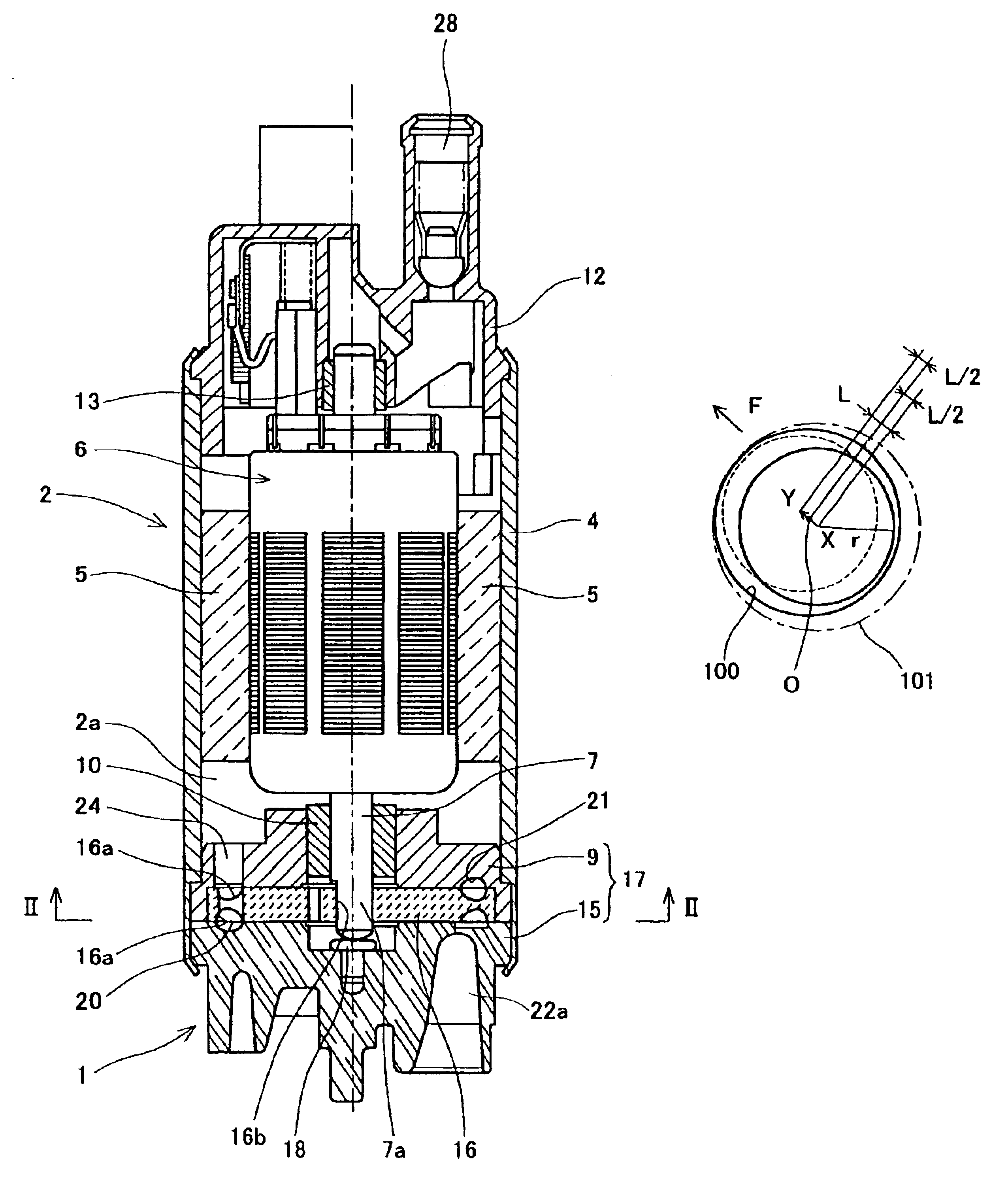
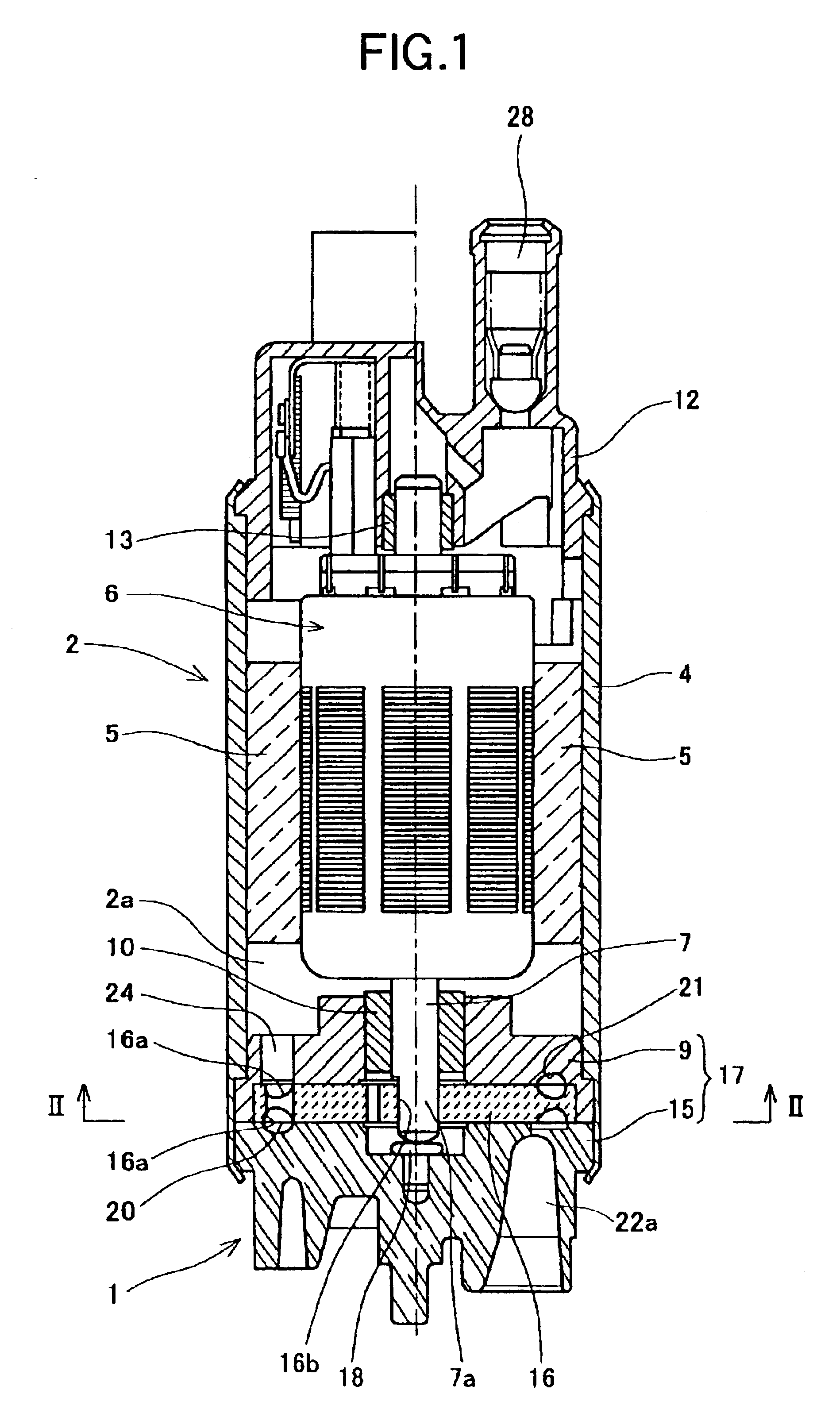
FIG. 1 is a sectional view of the fuel pump. In the figure, the fuel pump has a pump part 1 and a motor part 2 for driving the pump part 1. The motor part 2 comprises a brush DC motor. The motor part 2 has an approximately circular cylinder-shaped pump housing 4. A magnet 5 is disposed in the pump housing 4. A rotor 6 is disposed in the pump housing 4 in concentric relation to the magnet 5.

The rotor 6 has a shaft 7. The lower end portion of the shaft 7 is rotatably supported through a bearing 10 by a pump cover 9 secured to the lower end portion of the pump housing 4. The upper end portion of the shaft 7 is rotatably supported through a bearing 13 by a motor cover 12 secured to the upper end portion of the pump housing 4.

In the motor part 2, the rotor 6 is rotated by su...


PUM


Abstract

A fuel pump capable of using the pump efficiency most efficiently without reducing the useful service life is provided. A relatively large clearance allowing for the expected amount of wear is ensured in a region where the flow passage groove pressure is low. In a region where the flow passage groove pressure is high, it is unnecessary to allow for the wear. Therefore, the clearance is set relatively small.

Description

BACKGROUND OF THE INVENTION1. Field of the InventionThe present invention relates to a fuel pump adapted to suck in and pressurize a fuel such as gasoline and discharge the pressurized fuel.2. Discussion of Related ArtA fuel pump has an impeller and a pump casing, as disclosed in Japanese Patent Application Unexamined Publication (KOKAI) No. Hei 7-279881. The impeller has an approximately disk-shaped configuration with a plurality of blade grooves formed serially in a region extending along the outer peripheries of the obverse and reverse sides of the disk-shaped impeller. The impeller is rotated by a driving device such as a motor. The pump casing surrounds the impeller and has a circumferentially extending recess for forming a circumferentially extending flow passage groove between the same and the blade grooves of the impeller. The pump casing further has a suction opening communicating with the upstream end of the recess and a discharge opening communicating with the downstream ...

Claims


Application Information

Patent Timeline
IPC IPC(8): F04D5/00F04D7/02F04D29/22F04D29/44
CPCF04D5/002
Inventor USUI, TAKAYUKINAGASAKA, KENZOIWATA, KOICHI
Owner AISAN IND CO LTD
Why Eureka
Try Eureka