
Fast electric connector plug

a technology of electric connectors and plugs, applied in the direction of multi-conductor cable end pieces, coupling device connections, contact members penetrating/cutting insulation/cable strands, etc., can solve problems such as inconvenient control of wire positions, and achieve the effect of easy control of wire positions

Inactive Publication Date: 2005-01-04
SURTEC INDS
View PDF7 Cites 22 Cited by
  • Summary
  • Abstract
  • Description
  • Claims
  • Application Information

AI Technical Summary

Benefits of technology

An objective of the invention is to improve the structure of conventional plugs and provide a fast transmission electric connector plug that produces noise within the median value of the category 6 standard.
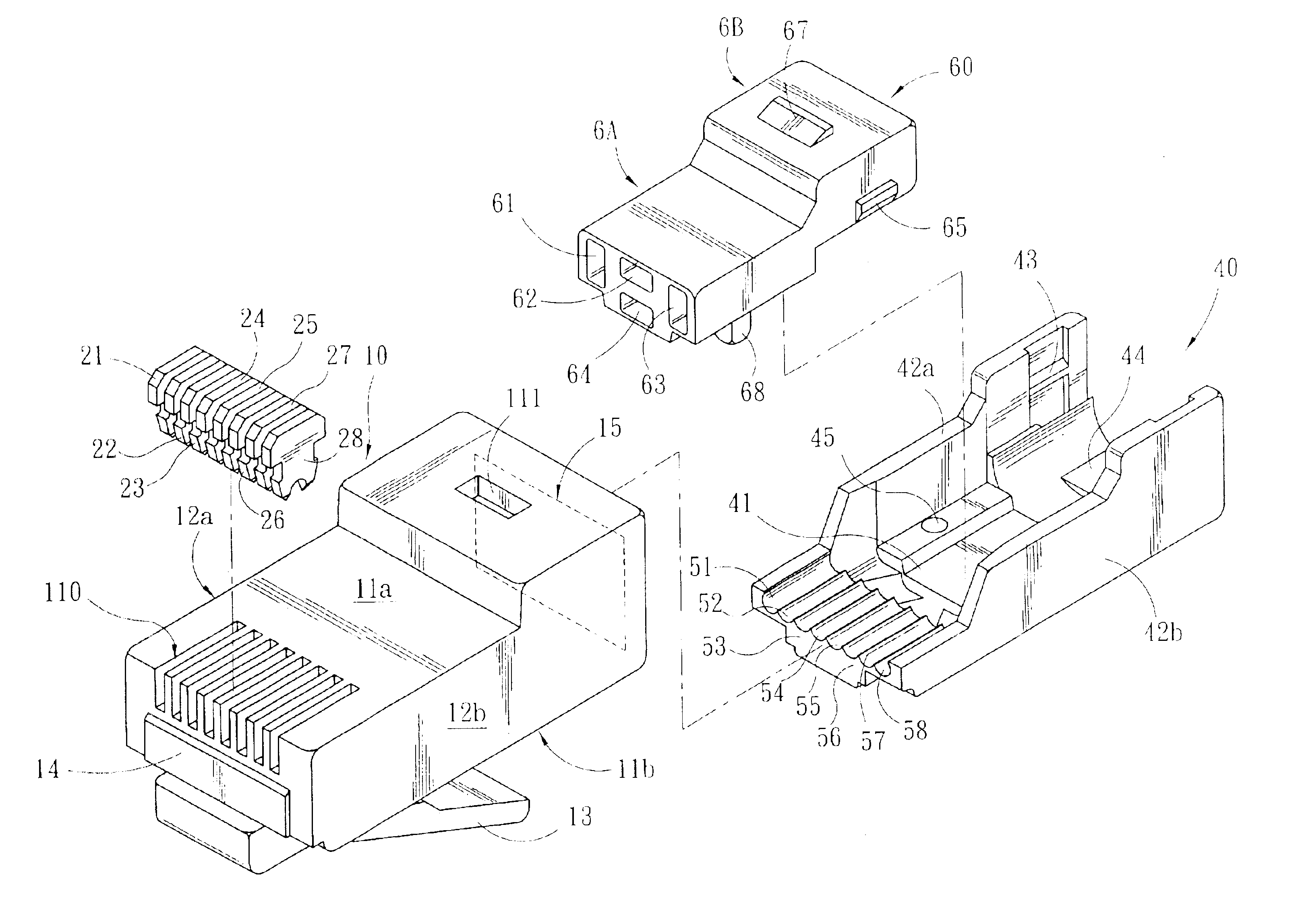
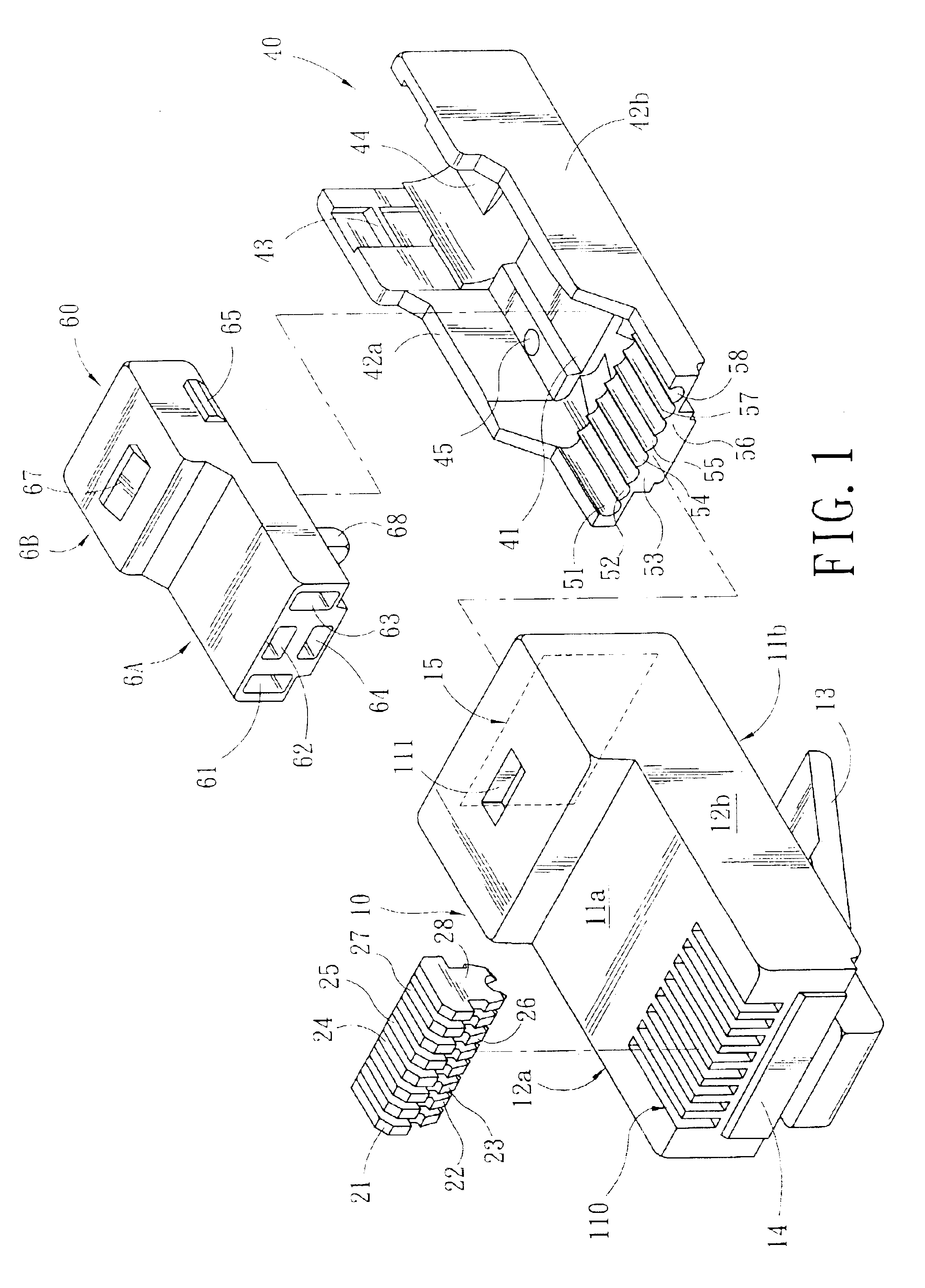
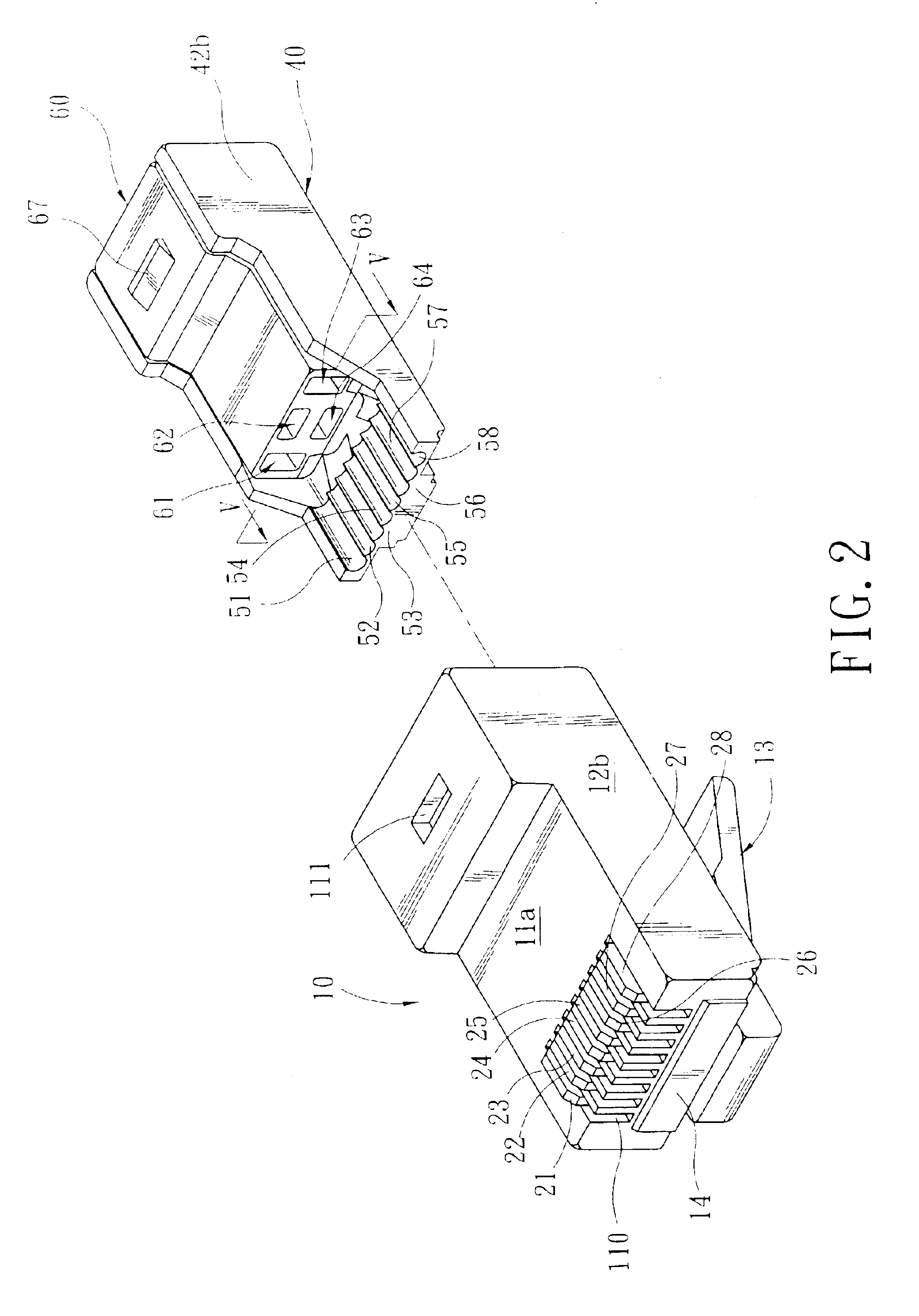
The invention uses an insertion element that can be put into an electric connector plug. This insertion element has several guide channels, which are distributed in four directions relative to the same central point. Each twisted pair of the fast communication cable is connected to the contacts at the front end of the plug under the guidance of the corresponding guide channel. The cross section of each guide channel is a long hole for a first twisted pair to pass through twisting and the other three twisted pairs to pass through in parallel. In this manner, the wire positions can be readily controlled. Besides, by closing the first wire to the eighth wire and the third wire to the sixth wire for creating compensation, the noise between the wires is kept within the median value of the category 6 standard.
To achieve the above objectives, the insertion element of the invention has two parts, including a carrier and a cover. The carrier and the cover tightly hold the fast communication cable before each twisted pair and the insertion element are installed inside the plug. This can prevent the end of any cable from being displaced due to friction in the assembly process, resulting in incorrect connections with the contacts.

Problems solved by technology

This can prevent the end of any cable from being displaced due to friction in the assembly process, resulting in incorrect connections with the contacts.

Method used


Image

  • Fast electric connector plug
  • Fast electric connector plug
  • Fast electric connector plug

Examples


Embodiment Construction

Please refer to FIG. 1. The disclosed electric connector plug has a plug shell 10 and an insertion element. The plug shell 10 is the same size as an RJ-45 electric connector plug. It is a hollow element with an upper wall 11a, a lower wall 11b, a left wall 12a, a right wall 12b, and an elastic chip 13 located at the bottom of the lower wall 11b and extending downwards. The elastic chip 13 is used to hold and connect with an electric connector jack (not shown). The front end in the insertion direction toward the electric connector jack is a closed front wall 14. The other end is an opening 15 to the exterior. The front end of the plug shell 10 has eight metal electrodes 21˜28. The metal electrodes 21˜28 are inserted from the insertion holes 110 at the front end of the upper wall 11a downward into the plug shell 10. They are connected with the twisted pairs 31˜38 of the fast communication cable 30 through the sharp front ends of the metal electrode 21˜28. The metal electrodes 21˜28 ar...


PUM


Abstract

A fast electric connector plug that produces noise within the median value of the category 6 (CAT-6) standard. Through an insertion element installed inside an electric connector plug, four twisted pairs of a CAT-6 cable are configured in four directions from the same central point. At the same time, the first twisted pair is kept twisted and the other three twisted pairs are parallel before reaching the contacts of the plug. The first wire and the eighth wire are kept close to the third wire and the sixth wire in order to produce a compensation effect and achieve more reliable fast data transmissions.

Description

BACKGROUND OF THE INVENTION1. Field of InventionThe invention relates to an electric connector plug and, in particular, to a fast electric connector plug that generates noise within the median value of the category 6 standard.2. Related ArtIn response to future network applications in the Ethernet, the U.S. Telecommunications industry Associations (TIA) released a CAT-6 standard (ANSI / TIA / EIA-568-B.2-1) in June 2000. The CAT-6 standard is expanded from 100 MHz of the CAT-5 standard to 200 MHz. Its capacity is also higher than that of CAT-5 by 25%. Therefore, the test frequency for CAT-6 cables may even reach 250 MHz. The biggest difference between CAT-6 and CAT-5 is the improvement in cross-talks and return losses. For new generation full duplex fast network applications, fewer return losses are very important. The cross-talk is a key factor for the best bandwidth. Although 100 Mbps is still the mainstream in current network setups, the CAT-6 standard will be more suitable for futur...

Claims


Application Information

Patent Timeline
Patent Type & Authority Patents(United States)
IPC IPC(8): H01R11/20H01R12/26H01R12/00H01R4/24H01R11/11H01R24/00H01R12/78
CPCH01R13/6477H01R13/6461Y10S439/941H01R24/64
Inventor CHEN, MICHAEL
Owner SURTEC INDS
Learn More