Racking system

a technology of racks and parts, applied in the field of racks, can solve the problems of limiting the convenient access of the operator to all faces of parts, affecting the operation of the operator, so as to achieve the effect of reducing the number of parts

Inactive Publication Date: 2005-01-04
PATRYKUS JOEL A
View PDF13 Cites 48 Cited by
  • Summary
  • Abstract
  • Description
  • Claims
  • Application Information

AI Technical Summary

Benefits of technology

It is a further feature of the present invention to provide a paint rack which is compact, and which can be readily broken down for shipping into a minimum number of parts.

Problems solved by technology

These body parts, formed of steel, aluminum, plastic, composites, or other material, are nonetheless subject to wear and corrosion by the elements, as well as structural damage by collision with other automobiles or objects.
In the event of damage, it is sometimes possible to repair and repaint a body part while it remains in place on the automobile.
Floor mounted racks cannot help but present obstacles to the free movement of the paint gun, thereby restricting the convenient access of the operator to all faces of the part.

Method used


Image

  • Racking system
  • Racking system
  • Racking system

Examples


Embodiment Construction

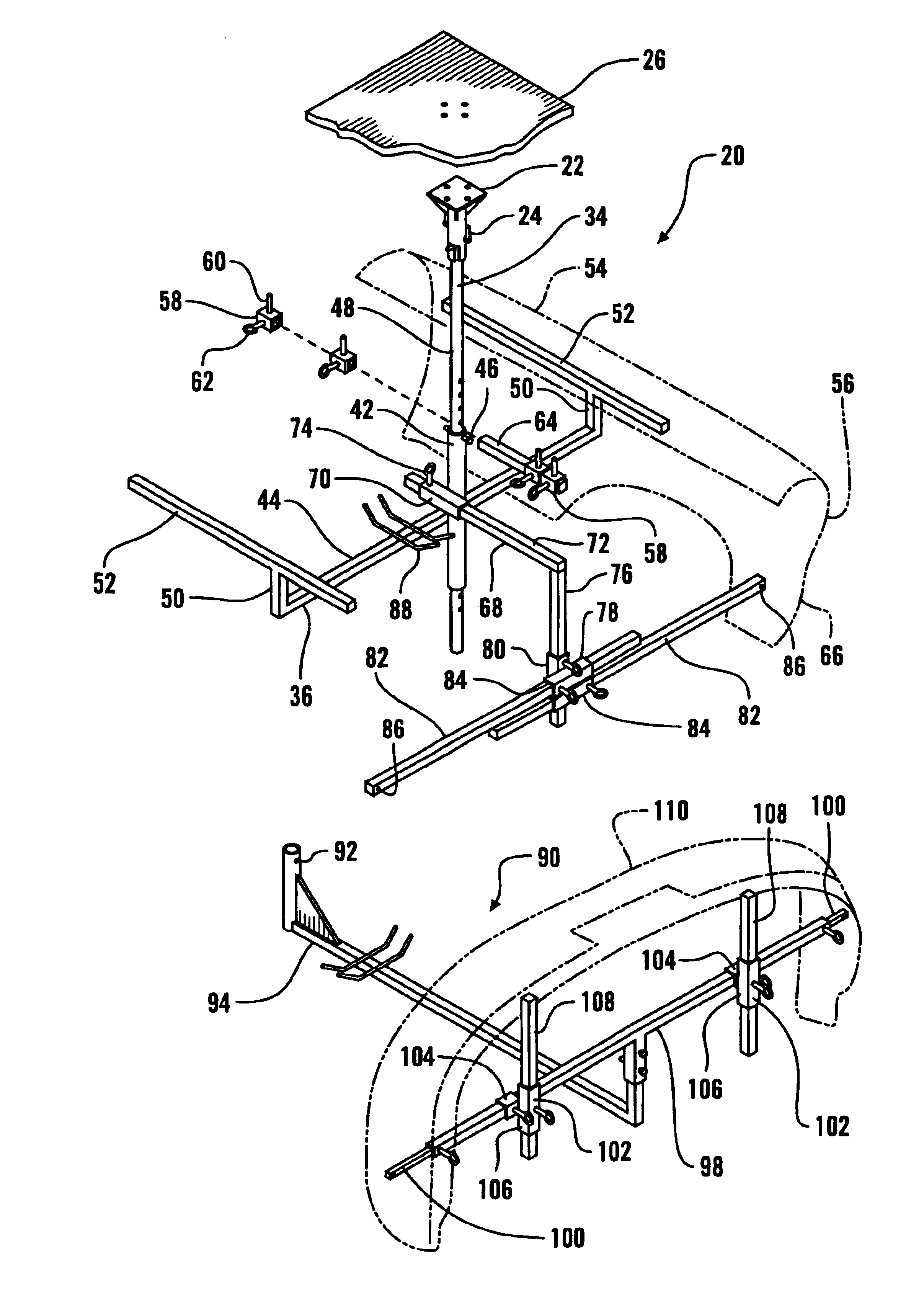
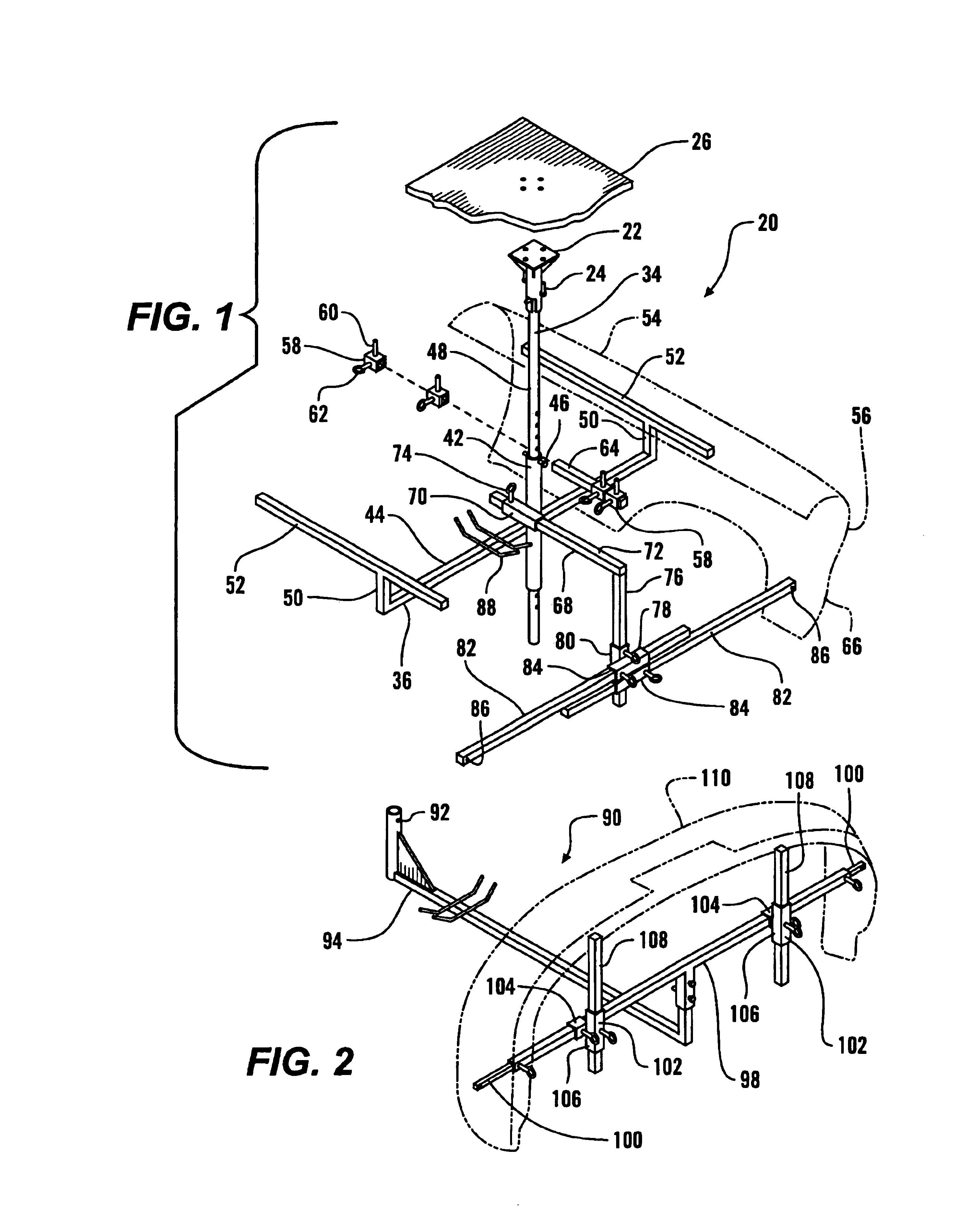
Referring more particularly to FIGS. 1-4, wherein like numbers refer to similar parts, a rack assembly 20 is shown in FIG. 1. The rack assembly 20 is supported from overhead by an overhead mounting bracket 22 which is connected by fasteners 24 to an overhead element 26 such as a ceiling truss or bean. As best shown in FIG. 4, the mounting bracket 22 has a base plate 28 from which a cylindrical pipe 30 extends downwardly. Four ribs 32 extend from the paper 30 to the base plate 28. The fasteners 24 extend through the base plate 28 to be secured within the overhead element 26. A vertical support tube 34 is engaged within the overhead mounting bracket 22 and extends downwardly to engage a central frame 36. The lower end of the mounting bracket 22 has two opposed inverted J-shaped slots 38 which open downwardly. The upper end of the vertical support tube 34 has two sidewardly protruding pins 40 which extend into the J-shaped slots 38 to enable the vertical support tube to be supported on...


PUM


Abstract

A support rack, such as for supporting automobile body parts during painting, may be supported entirely from overhead by a single vertical support tube received within an overhead mounting bracket. A central frame has a sidewardly projecting cross member, which supports side members which extend front to back. A front frame projects frontwardly of the cross member, and has adjustable side support arms. When a fender is supported on one of the side members by an upper edge, one of the side support arms can be adjusted to properly engage the fender. Alternatively, the rack's vertical mount tube can be supported from below on a wheeled support frame. Adjustable pin collars can be moved along the side arm to support parts which have mounting holes.

Description

CROSS REFERENCES TO RELATED APPLICATIONSNot applicable.STATEMENT AS TO RIGHTS TO INVENTIONS MADE UNDER FEDERALLY SPONSORED RESEARCH AND DEVELOPMENTNot applicable.BACKGROUND OF THE INVENTIONThe present invention relates to racks in general, and more particularly to racks for supporting objects for spray treatment such as in painting.The modern automobile, as it comes from the manufacturer, presents a variety of exterior parts and body panels which are attractively finished to present an even and durable surface which resists the elements at the same time as it contributes to the public appearance of the vehicle. These body parts, formed of steel, aluminum, plastic, composites, or other material, are nonetheless subject to wear and corrosion by the elements, as well as structural damage by collision with other automobiles or objects.In the event of damage, it is sometimes possible to repair and repaint a body part while it remains in place on the automobile. However, in many situation...

Claims


Application Information

Patent Timeline
Patent Type & Authority Patents(United States)
IPC IPC(8): B05B13/02F16M11/00
CPCB05B13/0285F16M11/00F16M11/043F16M11/42F16M11/28Y10S269/909F16M2200/028
Inventor PATRYKUS, JOEL A.
Owner PATRYKUS JOEL A
Why Eureka
Try Eureka