Integrated sample-processing system
a sample processing system and sample technology, applied in the field of sample processing systems, can solve the problems of large number of samples with significant shortcomings, prior systems may not have the flexibility to process sample holders with different sample densities, and sensitive or accurate processing of sample holders with very small samples,
- Summary
- Abstract
- Description
- Claims
- Application Information
AI Technical Summary
Problems solved by technology
Method used
Image
Examples
example 4
d. Example 4
Positive-Displacement Syringe Pump with a Rectangular Array of PTFE Nozzles
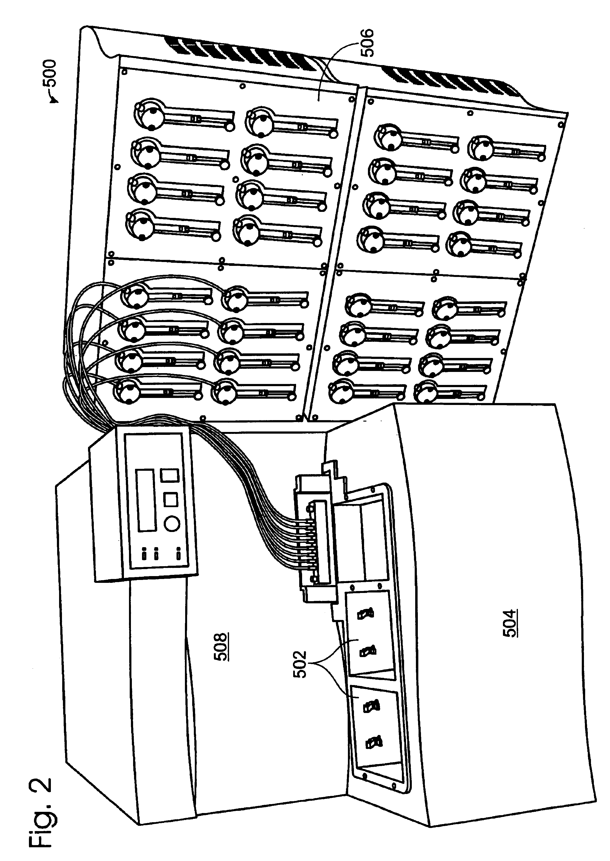
FIG. 28 shows yet another alternative noncontact fluid dispenser 3300 constructed in accordance with aspects of the invention. FIG. 28 is a schematic view of the fluid dispenser shown (together with a transport module and an analysis module) in FIG. 2 as part of an integrated system for preparing and / or analyzing samples. Fluid dispenser 3300 may include a fluid reservoir station 3302, at least one pump 3304, and at least one noncontact dispense elements 3306. These components may function essentially as described above in the context of FIGS. 25, 26, and / or 27. In use, the pumps direct fluid from the fluid reservoir station through the dispense elements and onto or into a sample holder such as a microplate 3308.
Fluid reservoir station 3302 may include bottles or fluid containers 3310 for holding buffers, reagents, samples, or other fluids for use in a particular assay. Fluid containers 3310 may v...
example 1
a. Example 1
FIG. 34 shows a pin transfer device 3700. Pin transfer device 3700 includes a pin 3702 and a mount 3703 configured to support the pin so that a tip 3704 of the pin is presented for fluid transfer. Pin transfer device 3700 may be used to transfer a small amount of a first liquid 3706 from a storage area 3708 to a second liquid 3710 in a receptacle 3712. This transfer may proceed in two steps:
Step 1. For loading, pin transfer device 3700 is positioned over storage area 3708 (Panel A), lowered until tip 3704 contacts first liquid 3706 (Panel B), and then raised until tip 3704 breaks contact with first liquid 3706 (Panel C). In the process, a drop 3714 of first liquid 3706 remains in contact with tip 3704 due to surface tension.
Step 2. For dispensing, pin transfer device 3700 is positioned over receptacle 3712 (Panel D), lowered until tip 3704 and drop 3714 contact second liquid 3710 (Panel E), and then raised until tip 3704 breaks contact with second liquid 3710 (Panel F). ...
example 2
b. Example 2
FIG. 35 shows an alternative pin transfer device 3750. Pin transfer device 3750 includes a plurality of pins 3752 and a rigid mount 3754 configured to support the pins in a preselected array. The tips 3756 of pins 3752 lie approximately within a plane 3758. Pin transfer device 3750 is configured to transfer a drop of fluid 3760 simultaneously between arrays of storage areas and / or receptacles, such as wells 3762 in a microplate 3764. More specifically, the device is configured to transfer fluid substantially simultaneously between storage areas and receptacles by substantially simultaneously contacting the pins to the storage area(s) to load the fluid, and then substantially simultaneously contacting the loaded pins to the receptacle(s) to unload the fluid.
Unfortunately, pin transfer devices using a rigid array of pins may suffer from a number of shortcomings. For example, there may be variations in the dispensed volume if the receptacles do not lie in a single plane, be...
PUM
 Abstract
Description
Claims
Application Information
 - R&D
- Intellectual Property
- Life Sciences
- Materials
- Tech Scout
- Unparalleled Data Quality
- Higher Quality Content
- 60% Fewer Hallucinations
Browse by: Latest US Patents, China's latest patents, Technical Efficacy Thesaurus, Application Domain, Technology Topic, Popular Technical Reports.
© 2025 PatSnap. All rights reserved.Legal|Privacy policy|Modern Slavery Act Transparency Statement|Sitemap|About US| Contact US: help@patsnap.com


