Method for controlling deposition of dielectric films

a dielectric film and film technology, applied in chemical vapor deposition coatings, coatings, metallic material coating processes, etc., can solve the problems of increasing leakage current, affecting leakage characteristics, and conventional dielectrics such as silicon dioxide and silicon nitride may no longer be suitable for many devices, so as to increase the deposition rate of barium-strontium-titanate films, increase the deposition pressure, and increase the deposition rate

Inactive Publication Date: 2005-01-04
MICRON TECH INC
View PDF70 Cites 22 Cited by
  • Summary
  • Abstract
  • Description
  • Claims
  • Application Information

AI Technical Summary

Benefits of technology

The patent describes a method for adjusting the composition of a barium-strontium-titanate film during deposition by controlling the pressure of the deposition chamber. By maintaining the flow rate of the precursors and increasing the pressure, the amount of titanium in the film can be increased and the deposition rate can be increased. This method allows for better control over the composition of the film and improves the quality of the resulting material.

Problems solved by technology

The technical problem addressed in this patent is how to improve the performance of high dielectric constant films in semiconductor device manufacturing without compromising either their capacity or their leakage current characteristics. This needs to be achieved while still being able to vary the concentration of different elements in the film when depositing them using low deposition temperature chemical vapor deposition techniques. Current methods require expensive and time-consuming steps to adjust precursor flow ratios and often result in limited flexibility in terms of compositional variations. New methods are necessary to allow for more precise control over the stoichiometry of high dielectric constant films.

Method used


Image

  • Method for controlling deposition of dielectric films
  • Method for controlling deposition of dielectric films
  • Method for controlling deposition of dielectric films

Examples


Embodiment Construction

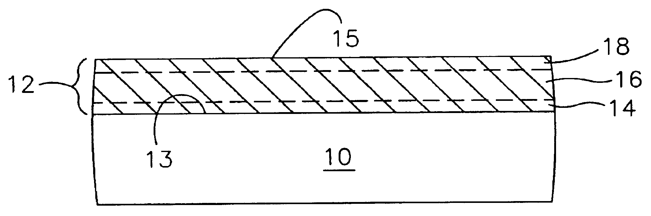
The present invention provides the ability to control stoichiometry in high dielectric constant films, for example, a high dielectric constant film such as a (Ba,Sr)TiO3 (barium-strontium-titanate or BST) film. FIG. 1 shows a high dielectric constant film 12 formed in accordance with the present invention. The high dielectric constant film 12 can be formed on a surface 13 of a substrate assembly 10.

As used herein, “substrate assembly” refers to either a semiconductor substrate, such as the base semiconductor layer, e.g., the lowest layer of a silicon material on a wafer, or a silicon layer deposited on another material, such as silicon on sapphire, or a semiconductor substrate having one or more films, layers, or structures formed thereon or regions formed therein. When reference is made to a “substrate assembly” in the following description, various process steps may have been previously used to form or define regions, junctions, various structures or features, and openings such as...


PUM

PropertyMeasurementUnit
Temperatureaaaaaaaaaa

Abstract

A method for controlling stoichiometry of dielectric films, e.g., BST films, preferably formed at low deposition temperatures. A deposition process may use an adjustment in oxidizer flow and/or partial pressure, the provision of a hydrogen-containing component, an adjustment in hydrogen-containing component flow and/or partial pressure, an adjustment in deposition pressure, and/or a modification of system component parameters (e.g., heating a shower head or adjusting a distance between a shower head of the deposition system and a wafer upon which the film is to be deposited), to control the characteristics of the dielectric film, e.g., film stoichiometry.

Description


Claims


Application Information

Patent Timeline
Owner MICRON TECH INC
Why Eureka
Try Eureka