
Feedforward amplifier with dual loop

a feedforward amplifier and loop technology, applied in the field of linear amplifiers, can solve the problems of poor linearity of the circuit, bias condition, and the inability to eliminate the nonlinear distortion component produced by the auxiliary amplifier, and achieve the effect of easy balance control

Inactive Publication Date: 2005-01-04
NTT DOCOMO INC
View PDF12 Cites 10 Cited by
  • Summary
  • Abstract
  • Description
  • Claims
  • Application Information

AI Technical Summary

Benefits of technology

It is therefore an object of the present invention to provide a feedforward amplifier which permits easy balance control of the distortion injection path including the feedforward-configured auxiliary amplifier.
According to the present invention, in the feedforward amplifier with a dual loop, the loop balance of the first auxiliary amplifier distortion detection circuit is controlled by the variable attenuator and the variable phase shifter inserted in the input path of the first auxiliary amplifier and the loop balance of the distortion elimination circuit is controlled by the variable attenuator and the variable phase shifter inserted in the input path of the first auxiliary amplifier distortion detection circuit. This brings the distortion elimination circuit into balance without affecting the balance of the first auxiliary amplifier distortion detection circuit, permitting compensation for the distortion component generated by the main amplifier and compensation for the distortion component produced by the first auxiliary amplifier.

Problems solved by technology

In general, when a semiconductor amplifying element of the amplifier is operated under the class-B bias condition, the linearity of the circuit is poorer than under the class-A bias condition.
With the above-described feedforward configuration, however, it is impossible to eliminate a nonlinear distortion component produced by the auxiliary amplifier.
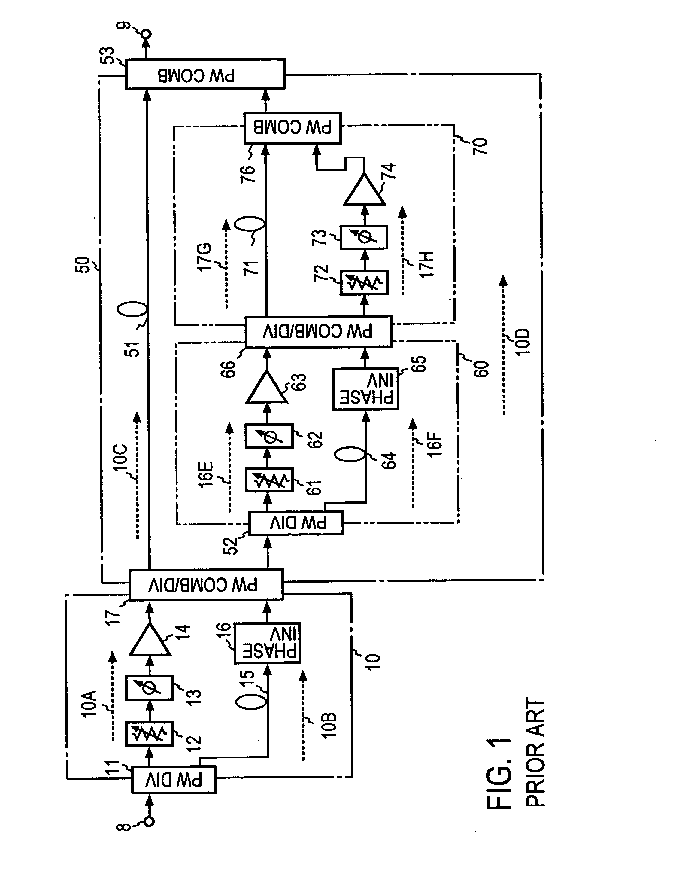
In practice, it is not easy to completely maintain the balance of the respective circuits with the distortion detection circuit 10 and the distortion elimination circuit 50.
Further, even if initialized perfectly, amplifier characteristics change with variations in ambient temperature, power supply and so forth, making it very difficult to stably maintain the above-mentioned circuits on well-balanced condition for a long period of time.
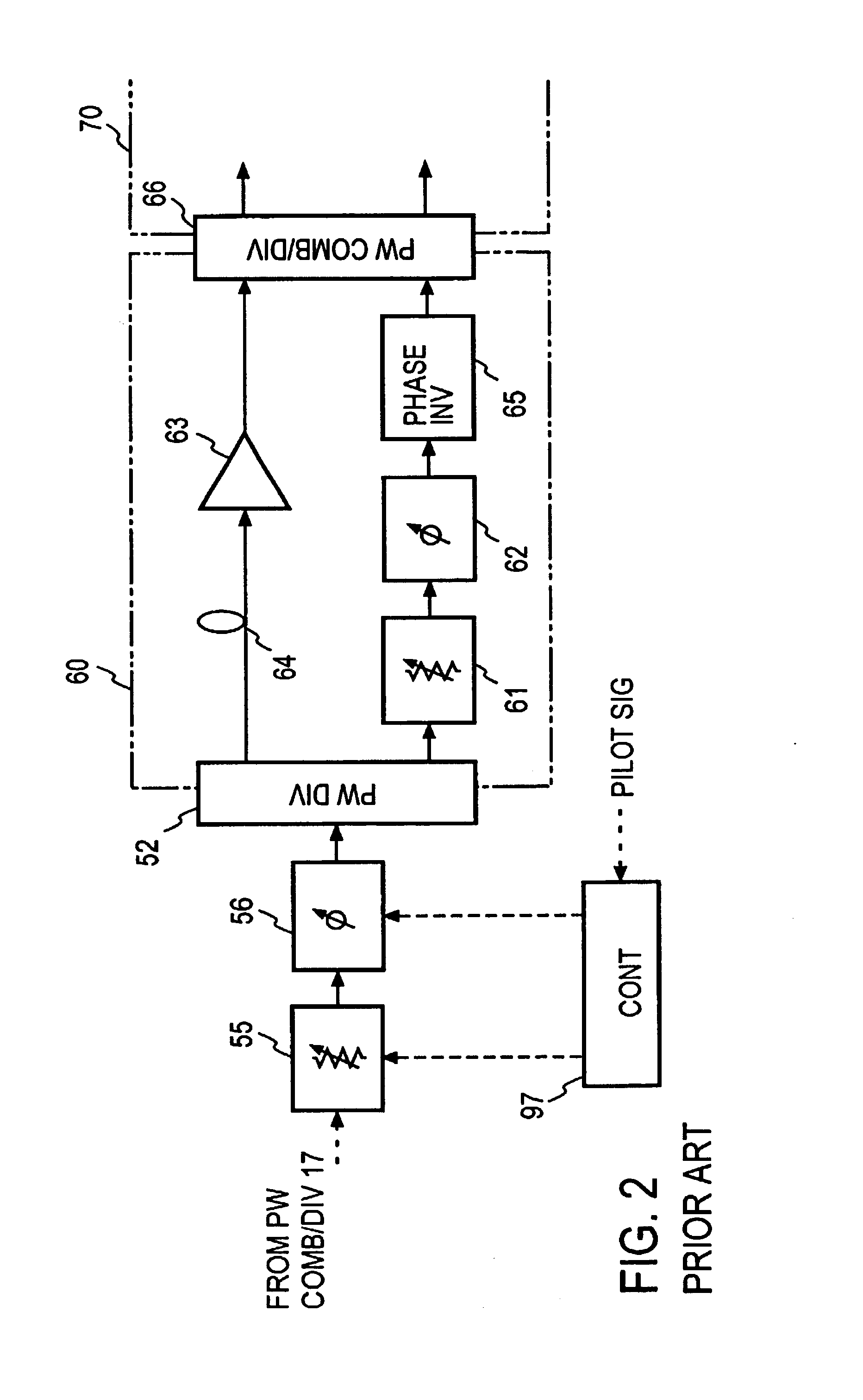
This presents a problem that even if the balance of the first auxiliary amplifier distortion detection circuit 60 is achieved by the variable attenuator 61 and the variable phase shifter 62, the balance of the distortion elimination circuit 50 cannot be achieved.
Moreover, there is a problem that when the balance of the distortion elimination circuit 50 is achieved, the balance of the first auxiliary amplifier distortion detection circuit 60 cannot be reached.

Method used


Image

  • Feedforward amplifier with dual loop
  • Feedforward amplifier with dual loop
  • Feedforward amplifier with dual loop

Examples


first embodiment

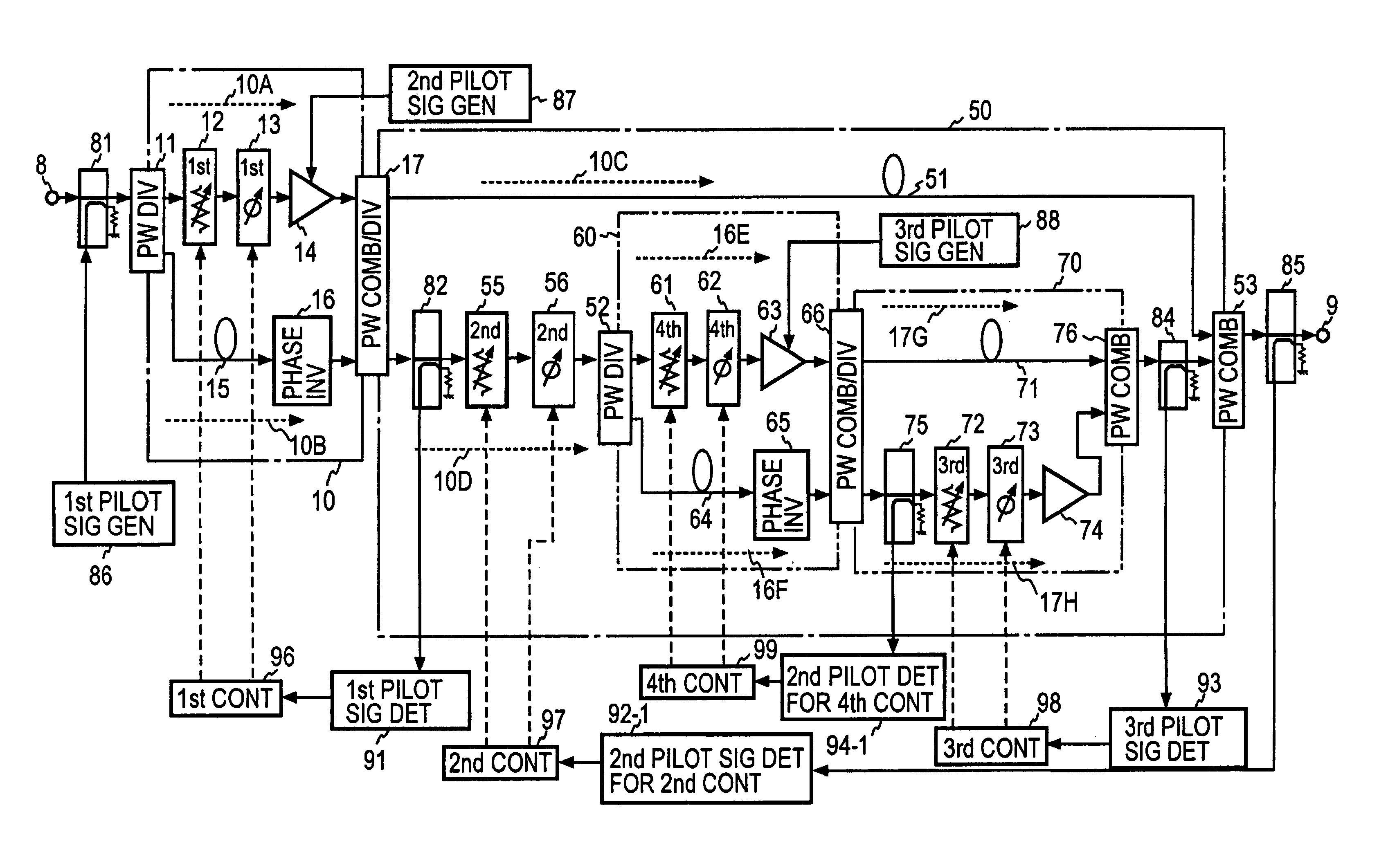
FIG. 3 illustrates in block form the feedforward amplifier according to the present invention, which uses three pilot signals and four control means.

As is the case with the feedforward amplifier of FIG. 1, the feedforward amplifier of this embodiment has the distortion detection circuit 10 and the distortion elimination circuit 50, and with a view to canceling the distortion produced by the first auxiliary amplifier 63 of the distortion elimination circuit 50, the first auxiliary amplifier 63 is feedforward-configured by providing the first auxiliary amplifier distortion detection circuit 60 and the first auxiliary amplifier distortion elimination circuit 70 in the distortion injection path 10D. The distortion detection circuit 10 comprises: the power divider 11 for dividing the amplifier input signal to the main amplifier signal path 10A and the linear signal transfer path 10B; the first variable attenuator 12, the variable phase shifter 13 and the main amplifier 14 inserted in the...


PUM


Abstract

In a feedforward amplifier with a dual loop in which a distortion injection path of a distortion elimination circuit 50 is provided as a feedforward configuration composed of a first auxiliary amplifier distortion elimination circuit 60 and a first auxiliary amplifier distortion elimination circuit, a second variable attenuator 55 and a second variable phase shifter 56 are provided preceding the distortion detection circuit 60, a second pilot signal injected between stages of a main amplifier 14 is detected by a directional coupler 85, and the second variable attenuator 55 and the second variable phase shifter 56 are controlled by a second controller 97 to minimize the level of the detected second pilot signal, thereby bringing the distortion elimination circuit and the first auxiliary distortion detection circuit into balance at the same time.

Description

BACKGROUND OF THE INVENTIONThe present invention relates to a linear amplifier for use mainly in the high-frequency band and, more particularly, to a feedforward amplifier with dual loop, which is provided with a distortion detection circuit for detecting distortion produced by a main amplifier, and a distortion elimination circuit which amplifies the detected distortion component by a first auxiliary amplifier and injects the amplified component into the output from the main amplifier to thereby cancel the distortion component and wherein the distortion elimination circuit comprises a distortion detection circuit which detects a distortion component produced by the first amplifier and a distortion elimination circuit which cancels the detected distortion component by its injection into the first auxiliary amplifier output.A radio base station for mobile communications employs a feedforward amplifier in a transmitting power amplifier. The feedforward amplifier is composed basically ...

Claims


Application Information

Patent Timeline
Patent Type & Authority Patents(United States)
IPC IPC(8): H03F1/32
CPCH03F1/3235H03F2201/3218H03F1/32
Inventor SUZUKI, YASUNORINOJIMA, TOSHIO
Owner NTT DOCOMO INC
Learn More