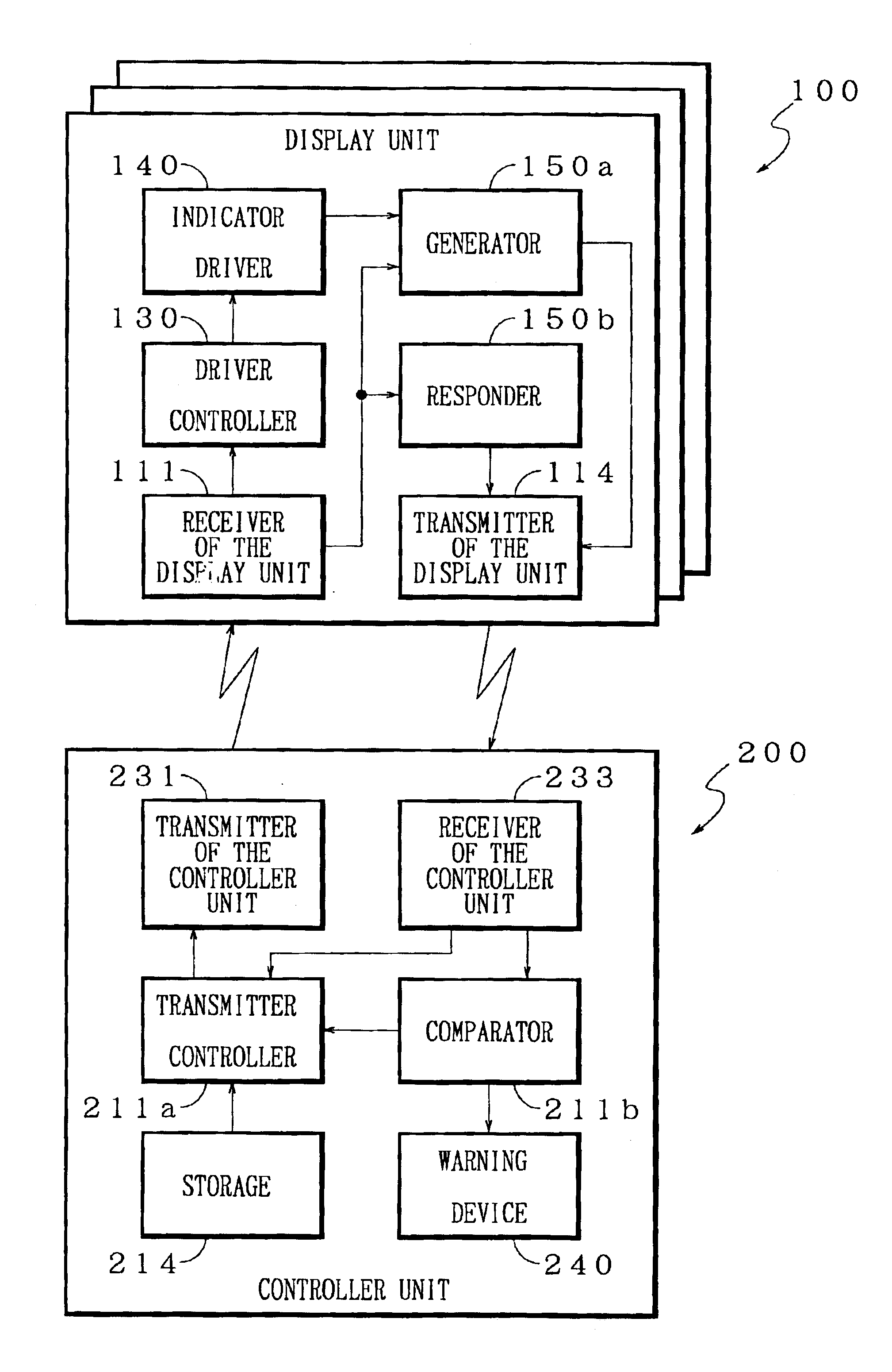
According to this aspect, in the display unit 100, when the measured data is received by the receiver of the display unit 111, the response data is generated by the generator 150a. Then, the response data is transmitted to the controller unit 200 by the transmitter of the display unit 114. Further, in the controller unit 200, when the response data is received by the receiver of the controller unit 233, the response data is compared to the transmitted measured data by the
comparator 211b. Then, according to the comparison result, the
comparator 211b judges whether the indicator driver 140 of the display unit 100 is controllable or not. Then, according to the judged result, the transmission of the measured data is controlled by the transmitter controller 211a. Accordingly, when the controller unit 200 transmits the measured data to the display unit 100, the display unit 100 generates the response data indicating the state of driving of the indicator driver 140 and transmits the response data to the controller unit 200. Therefore, because the controller unit 200 can recognize whether the each display unit 100 works normally or not, by a comparison of the received response data and the transmitted measured data, the controller unit 200 can cope with an abnormal state when the abnormal state occurs at the indicator driver 140. Namely, because the display unit 100 only needs to have a communication function and a function of driving according to the received measured data, and doesn't need to be aware of a communication state, the load of the display unit 100 can be reduced. Therefore, the display unit 100 can be made as a module corresponding to each object to be displayed such as a
speedometer independently, so that an arrangement of the display unit 100 can be given flexibility. Moreover, because the display system is controlled depending not only on the communication state between each display unit 100 and the controller unit 200, but also on the state of driving of the indicator driver 140 of each display unit 100, accuracy of the displaying contents can certainly be improved.
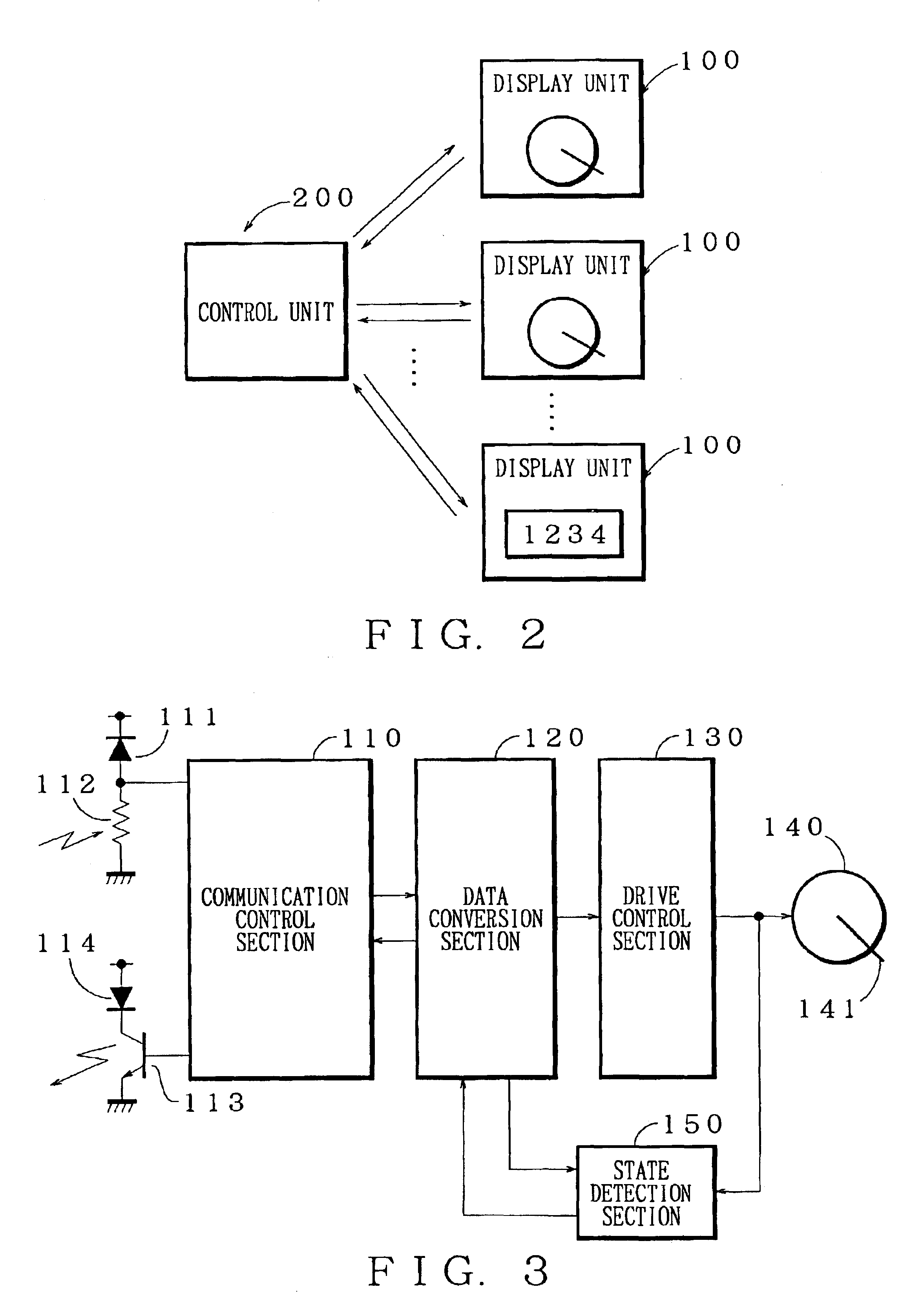
According to above described vehicle display system, the memory 214 memorizes in advance the
list of installation options listing the display units 100 having a feasibility to be installed. Further, the transmitter controller 211a so controls that the transmitter of the controller unit 231 transmits, for example at starting time of the control, the installation confirmation request to the display unit 100 listed by the
list of installation options and transmits the measured data only to the display unit 100 corresponding to respective display unit data which is received by the receiver of the controller unit 233 in response to the installation confirmation request. Therefore, the means for memorizing 214 memorizes the
list of installation options listing the display unit 100 having a feasibility to be installed. Then, the transmitter of the controller unit 231 transmits the installation confirmation request to the display unit 100 listed by the list of installation options. Then, the receiver of the controller unit 233 receives the display unit data in response to the installation confirmation request to confirm the installation of said display unit 100. Then, the transmitter of the controller unit 231 transmits the measured data to the installed display unit 100, so that the controller unit 200 can be used in common. Resultingly, the component of said vehicle display system can be easily changed by such as adding or deleting the display unit 100.
According to above described vehicle display system, when the receiver of the display 111 receives the measured data under a process of detection of the initial position of indication such as zero position of the pointer moved by the indicator driver 140, the generator 150a generates the response data indicating that the indicator driver 140 is under the process of detection. Then, when the receiver of the controller unit 233 receives the response data, the transmitter controller 211a controls the transmitter of the controller unit 231 to transmit the measured data again. If the indicator driver 140 is a
stepper motor, the indicator driver 140 detects an initial position at starting time. In such a case, when receiving the measured data under said process of detection, the transmitter of the display 114 returns the response data indicating that the indicator driver 140 is under the process of detection, so that the controller unit 200 can recognize whether the display unit 100 is under the process of detection of the initial position or not. Therefore, this vehicle display system can prevent mis-recognition that the display unit 100 has some trouble. Moreover, because the display unit 100 ignores the received measured data until the detection is finished, no stepping out of the indicator driver 140 occurs and driving control of the indicator driver 140 can be simple. Therefore, the composition of the display unit 100 can be simpler and the controller unit 200 can control the displays of the plurality of display units 100 accurately.
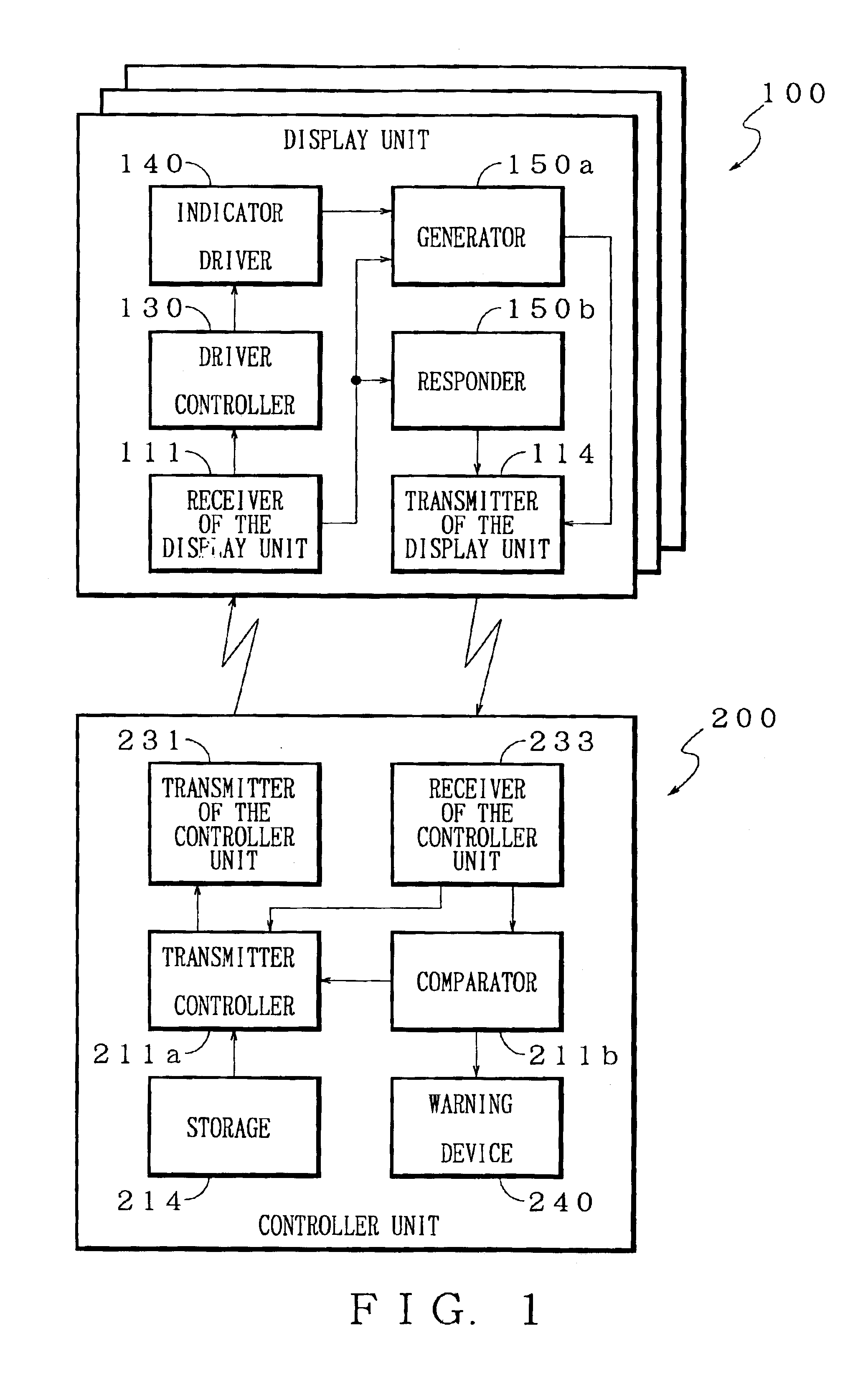
According to above described vehicle display system, the display units 100 are mounted on respective substrates to be arranged on an instrument panel of the vehicle. Therefore, by assembling the display units 100 on the respective substrates, a flexibility of arranging the display units 100 in an interior of the vehicle can be increased. Therefore, the arrangement of the display units 100 can be novel, so that commercial value of the vehicle display system can be increased.

