Speed change apparatus of vehicle

a technology of speed change and gear change, which is applied in the direction of mechanical control devices, manual control with single controlling member, instruments, etc., can solve the problems of time and effort, large shift lever device, and inability to adjust the turn position of the shift lever, so as to facilitate the design of the vehicle, increase the flexibility of the arrangement of the transmission and the shift lever device, and reduce the effect of manual control

Active Publication Date: 2015-10-29
KAWASAKI MOTORS LTD
View PDF2 Cites 0 Cited by
  • Summary
  • Abstract
  • Description
  • Claims
  • Application Information

AI Technical Summary

Benefits of technology

[0006]The present invention has been devised in view of the above-mentioned problems. An object thereof is to provide a speed change apparatus of a vehicle in which an adjustment for a turn position of the shift lever becomes easy, an arrangement flexibility of the shift lever increases, or the shift lever becomes compact.

Problems solved by technology

Therefore, shift lever device becomes large and complex.
Moreover, it takes time and effort to adjust the turn position of the shift lever 301.

Method used


Image

  • Speed change apparatus of vehicle
  • Speed change apparatus of vehicle
  • Speed change apparatus of vehicle

Examples


Embodiment Construction

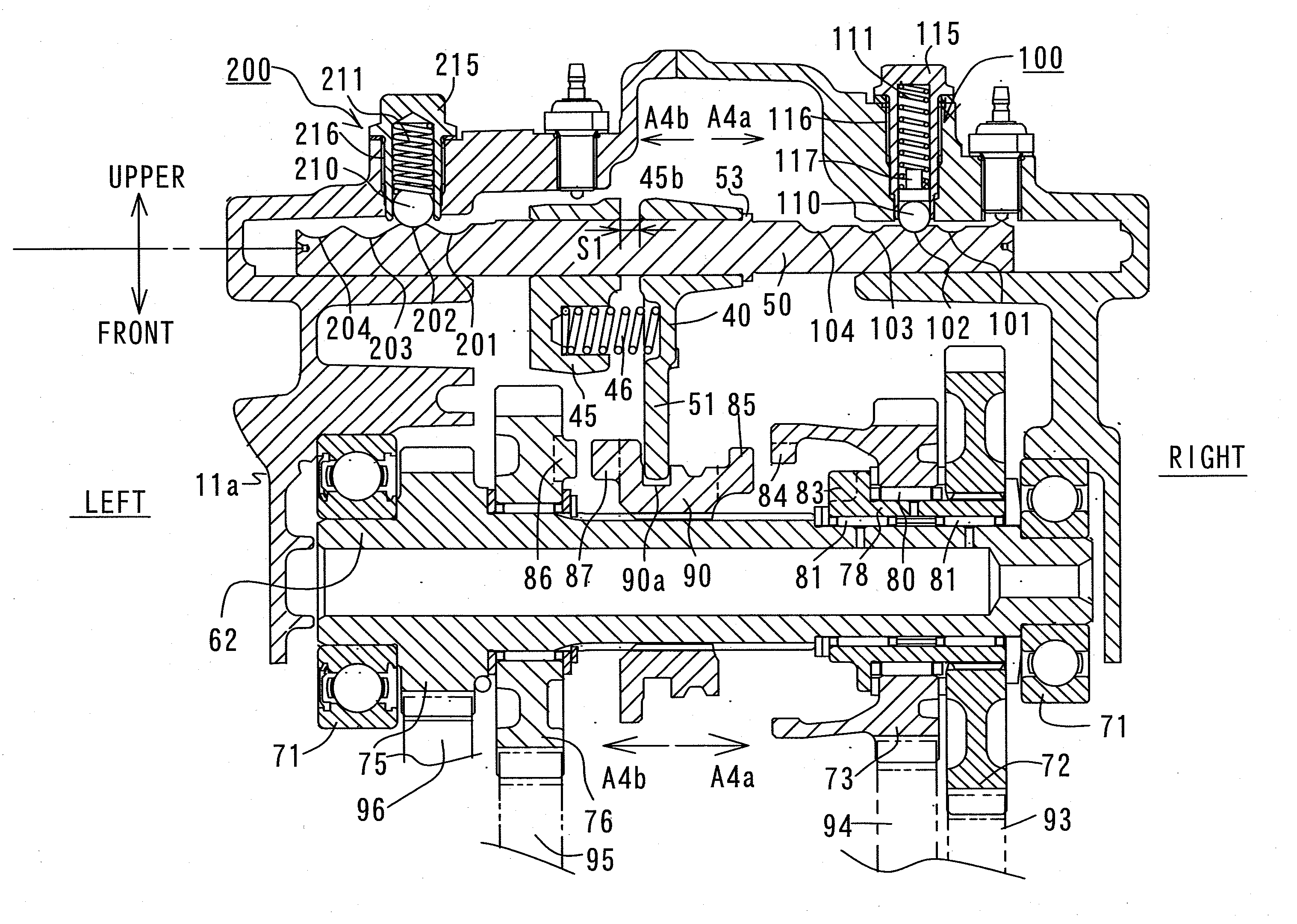
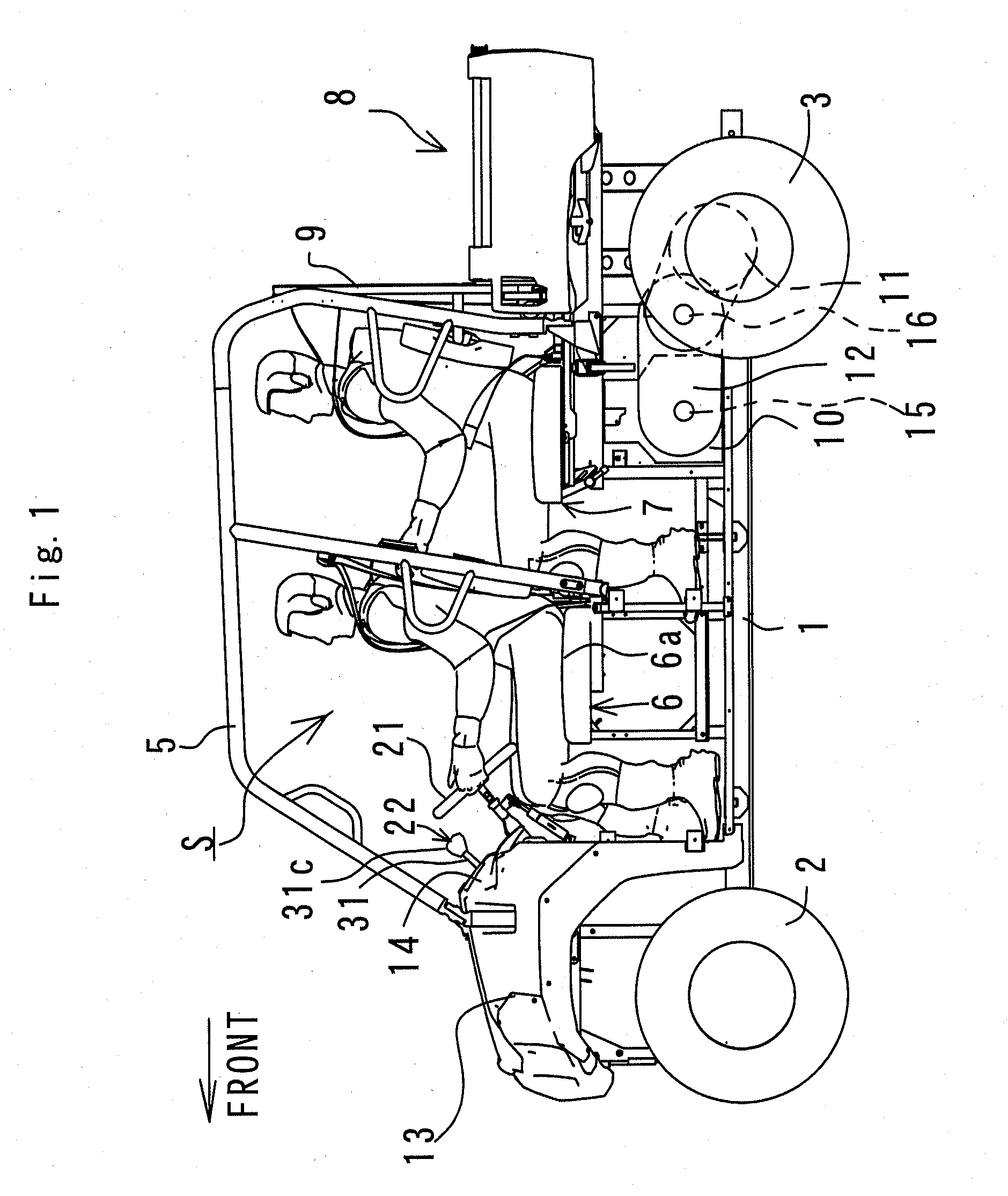
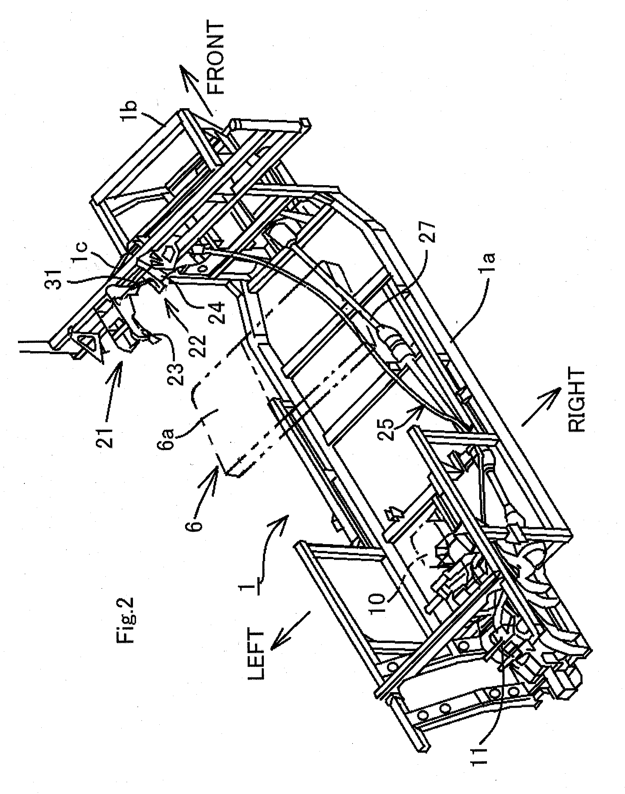
[0040]FIGS. 1 to 11 show a speed change apparatus according to the present invention and a utility vehicle including the speed change apparatus. Then, an embodiment of the present invention is described below with reference to these drawings. For convenience of description, a forward traveling direction of the utility vehicle will be described as a “front side or forward” of the utility vehicle and respective components, and a right and left direction viewed from a driver will be described as a “right and left direction” of the utility vehicle and the respective components.

[0041]In FIG. 1, a pair of right and left front wheels 2 is provided in a front portion of a vehicle body frame 1 of the utility vehicle, and a pair of right and left rear wheels 3 is provided in a rear portion of the vehicle body frame 1. A riding space S formed between the front wheels 2 and the rear wheels 3 is surrounded by a ROPS 5, where the ROPS 5 is an abbreviation of a rollover protective structure. A ben...


PUM


Abstract

A speed change apparatus for a vehicle includes a gear transmission, a shift lever device arranged in a zone where a driver on a driver's seat can operate the shift lever device, and an operation force transmission mechanism. The shift lever device is provided with a detent mechanism for positioning and holding the shift lever at each shift position, and an operation force transmission mechanism is constituted by a push pull cable.

Description

BACKGROUND OF INVENTION[0001]1. Field of the Invention[0002]The present invention relates to a speed change apparatus of a vehicle including a gear transmission, a shift lever device arranged in a zone where a driver on a driver's seat can operate the shift lever device, and an operation force transmission mechanism for transmitting an operation force of the shift lever device to the gear transmission.[0003]2. Description of the Prior Art[0004]FIG. 12 shows a shift lever device according to a conventional art described in JP Laid-open Publication No. 2006-082737. A shift lever 301 is turnable in a forward and rearward direction and in a right and left direction by two lever shafts 310, 311. The two lever shafts 310,311 are at right angles to one another. The shift lever 301 is connected to a shift device in a gear transmission (not shown) through a push pull cable 302. The shift device in the transmission is provided with a detent mechanism for holding a shift shaft at a shift posit...

Claims


Application Information

Patent Timeline
Patent Type & Authority Applications(United States)
IPC IPC(8): F16H63/38B60K20/08F16H61/36
CPCF16H63/38F16H2063/3076B60K20/08F16H61/36F16H2061/242
Inventor ITOO, SEIJIHAMADA, AYUMIMORITA, TAISUKETAKAGI, JUN
Owner KAWASAKI MOTORS LTD
Why Eureka
Try Eureka