Antenna for a communication terminal

a technology for communication terminals and antennas, which is applied in the direction of resonant antennas, elongated active elements, and protection materials radiating elements, etc. it can solve the problems of unavoidable capacitance to ground and user hand detuning, so as to increase the “height” of the antenna and improve the current distribution of the antenna

Inactive Publication Date: 2005-01-04
QISDA CORP
View PDF4 Cites 41 Cited by
  • Summary
  • Abstract
  • Description
  • Claims
  • Application Information

AI Technical Summary

Benefits of technology

Such capacitive loading at the end of the first printed conductor pattern section leads to an improvement in the current distribution of the antenna. The capacitive loading in this case has the effect of virtually lengthening the entire antenna so that the deviation of the effective length from the ideal length can be compensated for by the capacitive loading. This does not increase the “height” of the antenna since the phasing lines of the capacitive load extend mainly transversely to the height.
Depending on requirements, the second printed conductor pattern section can be constructed symmetrically or asymmetrically with respect to the first printed conductor pattern section. In contrast to a symmetric construction, asymmetry in the second printed conductor pattern section leads to a superposition of two waves with slightly different phase angles due to the two points of reflection at the ends of the top-loading capacitance being spaced differently from the first printed conductor pattern section. On the one hand, this leads to a reduction in the quality factor of the antenna but, on the other hand, it leads to a desirable increase in the bandwidth.

Problems solved by technology

The capacitive loading thus has a similar effect to the top-loading capacitances known from the field of “normal” broadcast antenna construction, which are arranged at the top end of vertical monopole rod antennas erected on buildings, etc., but it must be considered additionally in this case that, due to the small geometric dimensions and the vicinity to the shield cover, the circuit board, the battery pack or other parts of the device, unavoidable capacitances to ground of the device occur and, in addition, the detuning by the hand of the user as mentioned occurs.

Method used


Image

  • Antenna for a communication terminal
  • Antenna for a communication terminal
  • Antenna for a communication terminal

Examples


Embodiment Construction

Since the main field of use of the antennas 10 according to the present invention is in the field of mobile telephones, wherein it offers particularly great advantages, particularly because of the problems of the antenna being covered by the hand of the user, the following exemplary embodiments are based on antennas for mobile telephones. However, it is pointed out again that, naturally, the use of such antennas is not restricted to mobile telephones.

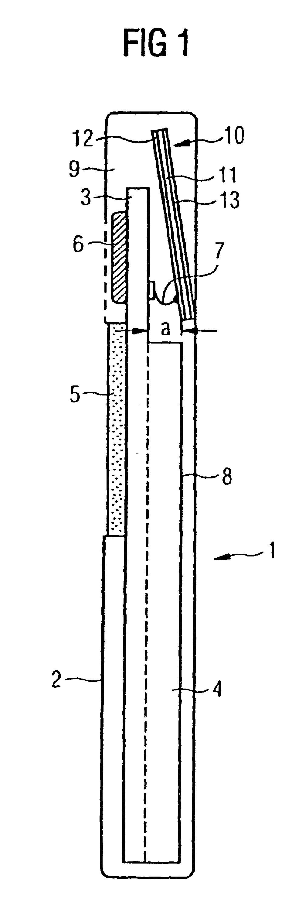
FIG. 1 shows such a typical mobile telephone 1 with a casing 2 and an integrated antenna 10 according to the present invention. The other components of the mobile telephone 1 are shown only partially and diagrammatically. On the one hand, the mobile telephone exhibits a main circuit board 3 on which the earphone capsule 6 is arranged in the upper area and below that the display 5. Below the display 5, there is the keypad (not shown). At the rear of the main circuit board 3, the battery pack 4 is arranged, among other things. The main ci...


PUM


Abstract

An antenna for the communication terminal having a printed conductor pattern applied to a support, wherein the printed conductor pattern includes a first printed conductor pattern section, the end of which is capacitively loaded by a second printed conductor pattern section for tuning the antenna to a desired radio channel.

Description

The present invention relates to an antenna for a communication terminal having a printed conductor pattern applied to a support, and a communication terminal including such an antenna.BACKGROUND OF THE INVENTIONAs the miniaturization of mobile communication terminals, particularly mobile telephones, increases, antennas with smaller and smaller dimensions will be needed in the future. In the field of mobile telephones, therefore, so-called “stub antennas,” which only protrude out of the casing for a short distance, have mainly been used in recent times. These “stub antennas” have the disadvantage that they are mechanically sensitive and can break off. In addition, the antennas should also disappear visually as completely as possible in the miniaturized casing for design reasons. One possibility of completely integrating antennas consists in using antennas of the type mentioned initially, with a printed conductor pattern applied in or to a support; for example, so-called “PCB (printe...

Claims


Application Information

Patent Timeline
Patent Type & Authority Patents(United States)
IPC IPC(8): H01Q1/38H01Q9/04H01Q5/00H01Q1/24H01Q1/36H01Q9/40H01Q9/42H01Q5/371H01Q5/378
CPCH01Q1/243H01Q1/36H01Q1/38H01Q5/378H01Q9/42H01Q5/371H01Q9/40
Inventor HUBER, STEFANOELSCHLAGER, MARTINSCHREIBER, MICHAEL
Owner QISDA CORP
Why Eureka
Try Eureka