Cell bottom structure of electrolytic cell

An electrolytic cell and cell bottom technology, which is applied in the field of aluminum electrolytic cells, can solve the problems of complex force conditions on the tank shell and its surrounding, complex electrolytic cell shell structure, and impact on the state safety of the electrolytic cell. The effect of small fluctuations, design and material simplification

Inactive Publication Date: 2011-07-13
GUIYANG AL-MG DESIGN & RES INST
View PDF5 Cites 3 Cited by
  • Summary
  • Abstract
  • Description
  • Claims
  • Application Information

AI Technical Summary

Problems solved by technology

Under the action of the magnetic field, the horizontal current is easy to form a swirling flow of the aluminum liquid and produce a large wave peak, which affects the stable operation of the electrolytic cell on the one hand; , the cell voltage rises to increase power consumption; at the same time, the cathode carbon block is arranged horizontally, and the stress on the cell shell and the surrounding area is complicated due to thermal expansion and sodium absorption expansion, resulting in a complex structure of the electrolytic cell shell; The electric current gathers to the edge of the cell, which affects the safety of the cell state of the electrolytic cell, resulting in a large amount of steel used in the cell state

Method used


Image

  • Cell bottom structure of electrolytic cell
  • Cell bottom structure of electrolytic cell
  • Cell bottom structure of electrolytic cell

Examples


Embodiment 1

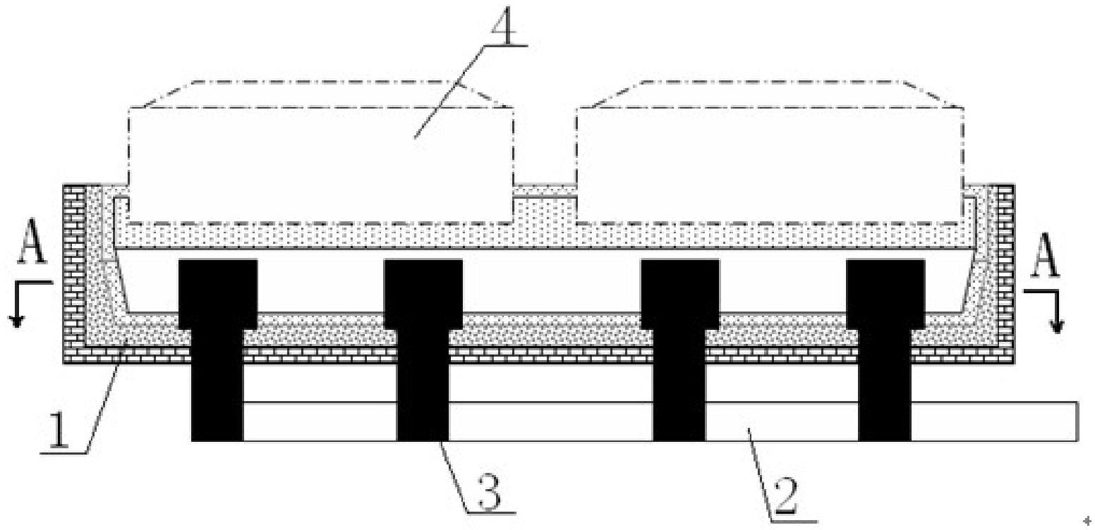
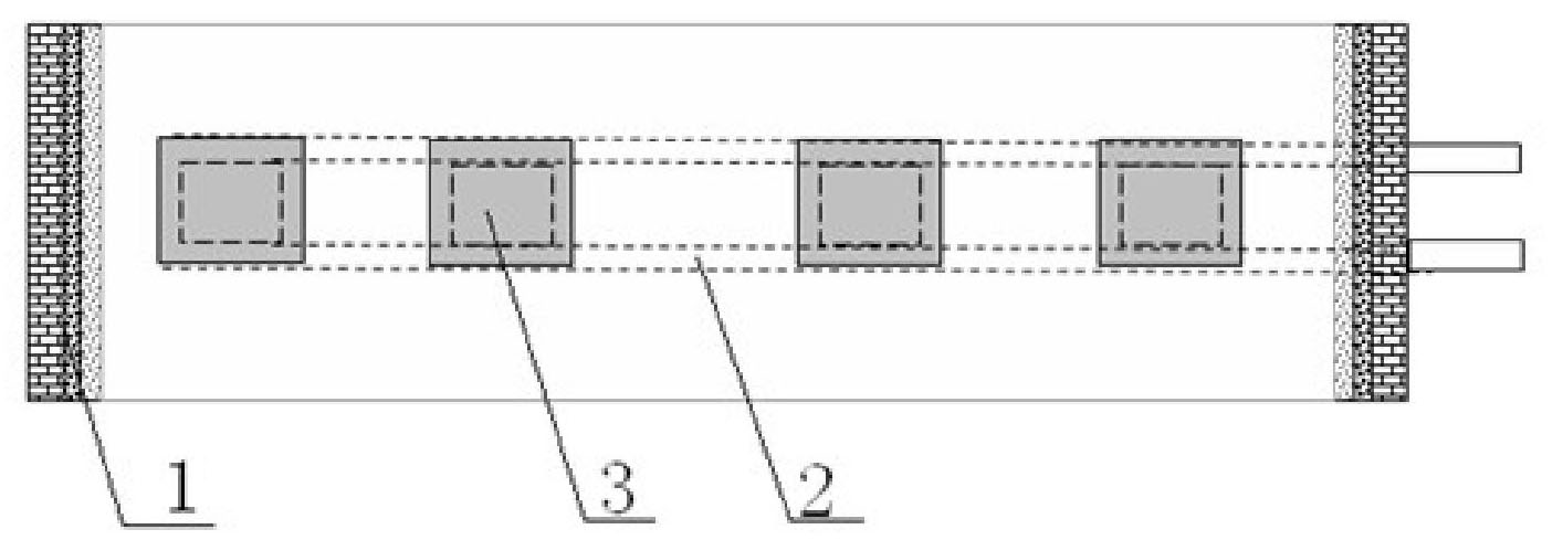
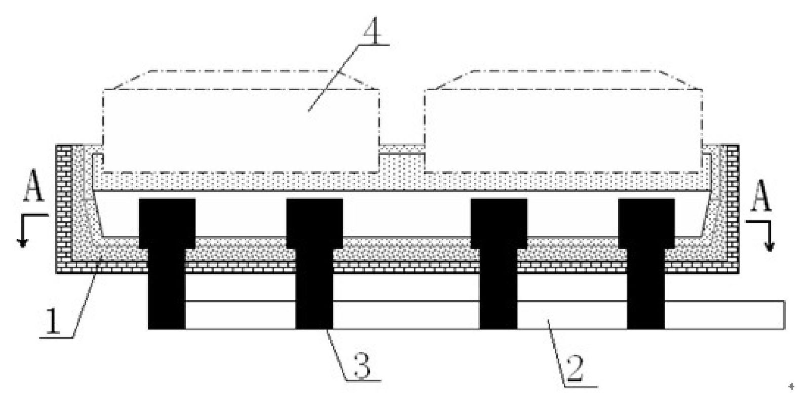
[0013] Embodiment 1: as figure 1 and figure 2 As shown, in the design of the electrolytic cell, the cathode is made into a columnar cathode carbon block 3, and the shape of the columnar cathode carbon block 3 is a quadrangular prism or a stepped quadrangular prism. When placing the columnar cathode carbon block 3 Place the columnar cathode carbon block 3 vertically on the bottom of the electrolytic cell 1, the length of the upper end of the vertically placed columnar cathode carbon block 3 extending into the aluminum liquid of the electrolytic cell 1 is 5-200mm, and the length of the columnar cathode carbon block 3 The lower end is connected with the cathode busbar 2 by bolts. When placing and installing the columnar cathode carbon block 3 perpendicular to the bottom of the electrolytic cell, the columnar cathode carbon block 3 is installed below the anode carbon block 4, the number of columnar cathode carbon blocks 3 below each anode carbon block 1 1 to 4 blocks, the speci...


PUM

PropertyMeasurementUnit
lengthaaaaaaaaaa

Abstract

The invention discloses a cell bottom structure of an electrolytic cell. The cell bottom structure comprises an electrolytic cell (1) and a cathode bus (2), wherein the bottom of the electrolytic cell (1) is provided with columnar cathode carbon blocks (3) which are perpendicular to the bottom of the electrolytic cell (1); and the lower ends of the columnar cathode carbon blocks (3) are connected with the cathode bus (2). In the cell bottom structure, the column cathode carbon blocks are vertically inserted in the bottom of the electrolytic cell, and the lower ends of the columnar cathode carbon blocks are connected with the cathode bus, so that current which is led in from anode carbon blocks is led out downwards from the columnar cathode carbon blocks through molten aluminum to reduce horizontal current in the molten aluminum; and a cathode which extends into the molten aluminum can effectively reduce fluctuation of the molten aluminum, so that a stable molten aluminum surface is achieved to reduce polar distance between the cathode and an anode and reduce the cell voltage to fulfill the aim of reducing power consumption.

Description

technical field [0001] The invention relates to a tank bottom structure of an electrolytic cell, belonging to the technical field of aluminum electrolytic cells. Background technique [0002] In the production of prebaked electrolytic cells, most aluminum electrolytic cells use a flat bottom, and the cathode carbon block is placed horizontally. The current enters from the upper anode and is exported from the side of the cell to form a 90° bend, forming a large horizontal current in the aluminum liquid layer. . Under the action of the magnetic field, the horizontal current is easy to form a swirling flow of the aluminum liquid and produce a large wave peak, which affects the stable operation of the electrolytic cell on the one hand; , the cell voltage rises to increase power consumption; at the same time, the cathode carbon block is arranged horizontally, and the stress on the cell shell and the surrounding area is complicated due to thermal expansion and sodium absorption e...

Claims


Application Information

Patent Timeline
Patent Type & Authority Applications(China)
IPC IPC(8): C25C3/08
CPCC25C3/08
Inventor 包崇爱郑莆席灿明曹斌杨溢黄俊杨涛杨朝红
Owner GUIYANG AL-MG DESIGN & RES INST
Why Eureka
Try Eureka