

Holder for magnetic transfer apparatus
a magnetic transfer and apparatus technology, applied in the field of holders for magnetic transfer apparatuses, can solve the problems of reducing reliability, deteriorating tracking function, dropping signals in the transfer of magnetic information, etc., and achieves the effects of not excessive deformation, reducing wear of sealing members, and improving durability of second sealing portions
- Summary
- Abstract
- Description
- Claims
- Application Information
AI Technical Summary
Benefits of technology
Problems solved by technology
Method used
Image

Examples
Embodiment Construction
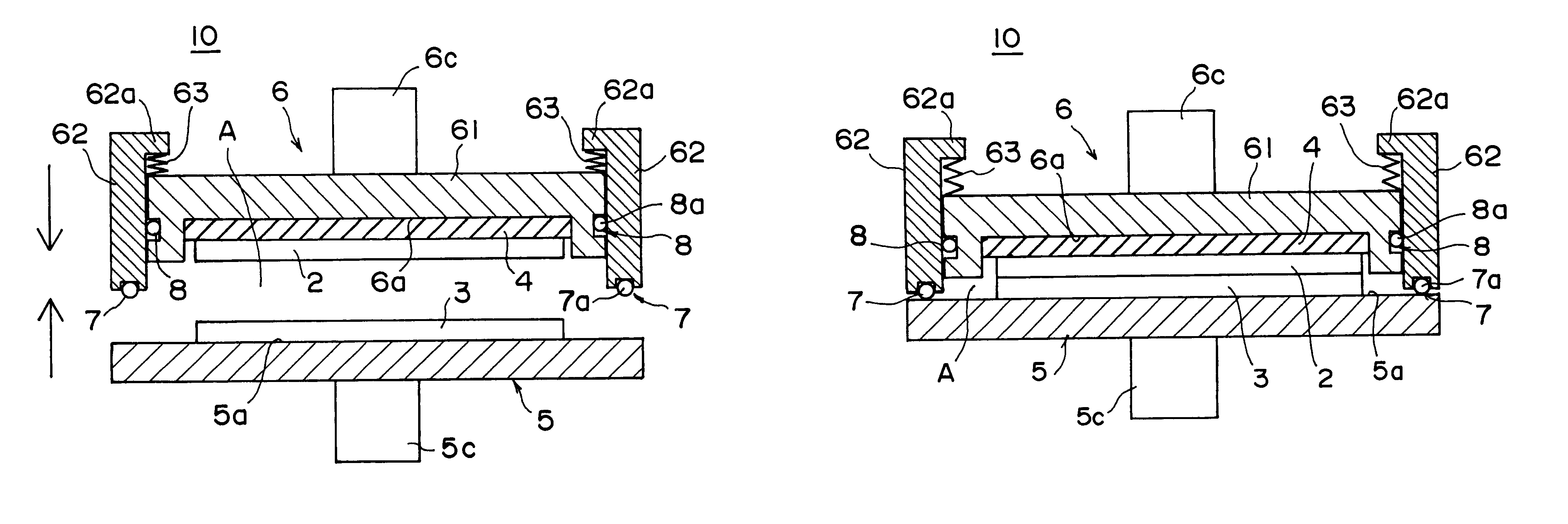
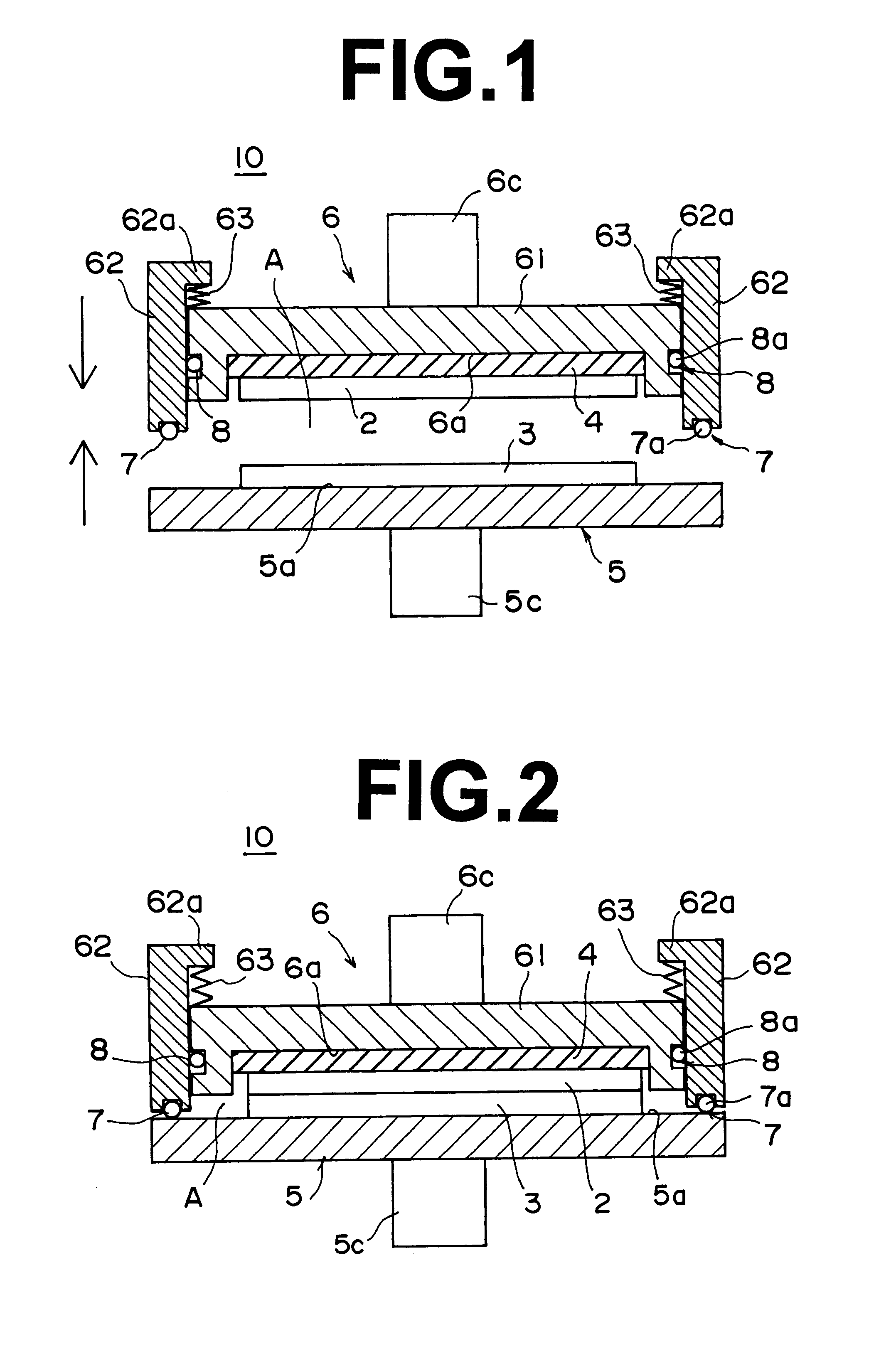
A holder 10 for a magnetic transfer apparatus in accordance with an embodiment of the present invention comprises a chamber base 5 and a chamber body 6 which are movable toward and away from each other. When the chamber base 5 and the chamber body 6 are brought into contact with each other, an inner space A is formed therebetween. A slave medium 2, a master information carrier 3 and an elastic member 4 are disposed in the inner space A and the slave medium 2 and the master information carrier 3 are brought into close contact with each other with their centers aligned with each other.
Though not shown, the magnetic transfer apparatus is provided with a vacuum means which evacuates the inner space A to a vacuum and a magnetic field application system which applies a transfer magnetic field to the holder 10 while rotating the holder 10.
Though the holder 10 shown in FIGS. 1 and 2 is for horizontally holding a slave medium 2 with a master information carrier 3 held in close contact with o...
PUM
 Abstract
Description
Claims
Application Information