X-ray computed tomography apparatus

a computed tomography and x-ray technology, applied in the direction of instruments, diaphragms/collimeters, diaphragms for radiation diagnostics, etc., can solve the problems of large amount of heat generated in the x-ray source, burden on patients, and inability to accurately rearrange images

Inactive Publication Date: 2005-01-04
CANON KK
View PDF13 Cites 14 Cited by
  • Summary
  • Abstract
  • Description
  • Claims
  • Application Information

AI Technical Summary

Benefits of technology

Therefore, an object of the present invention is to provide an X-ray computed tomography apparatus in which an X-ray shield is located between a focal point of an X-ray source and an X-ray detection device on a traveling path of X-rays which are entered from the focal point of the X-ray source onto the X-ray detecti

Problems solved by technology

Therefore, a large amount of heat is generated in the X-ray source to apply a large amount of load to the X-ray source.
In addition, an image taking time required for obtaining the

Method used


Image

  • X-ray computed tomography apparatus
  • X-ray computed tomography apparatus
  • X-ray computed tomography apparatus

Examples


Embodiment Construction

A preferred embodiment of the present invention will be described in detail in accordance with the accompanying drawings.

The following is an embodiment of an X-ray computed tomography apparatus in which scattered lines resulting from an object are removed to conduct a suitable image rearrangement.

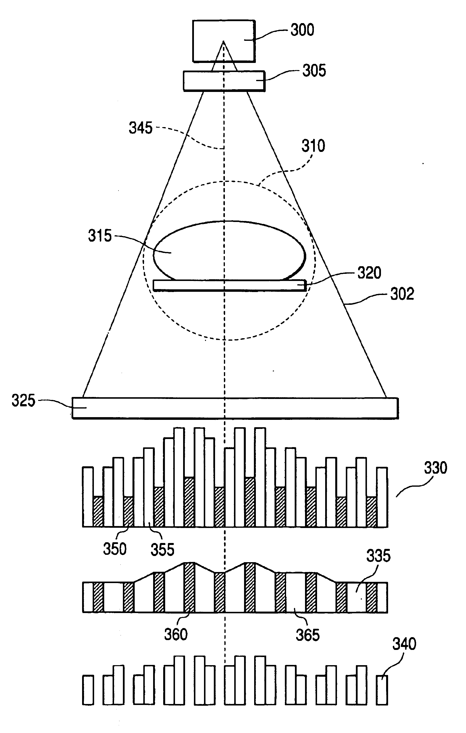
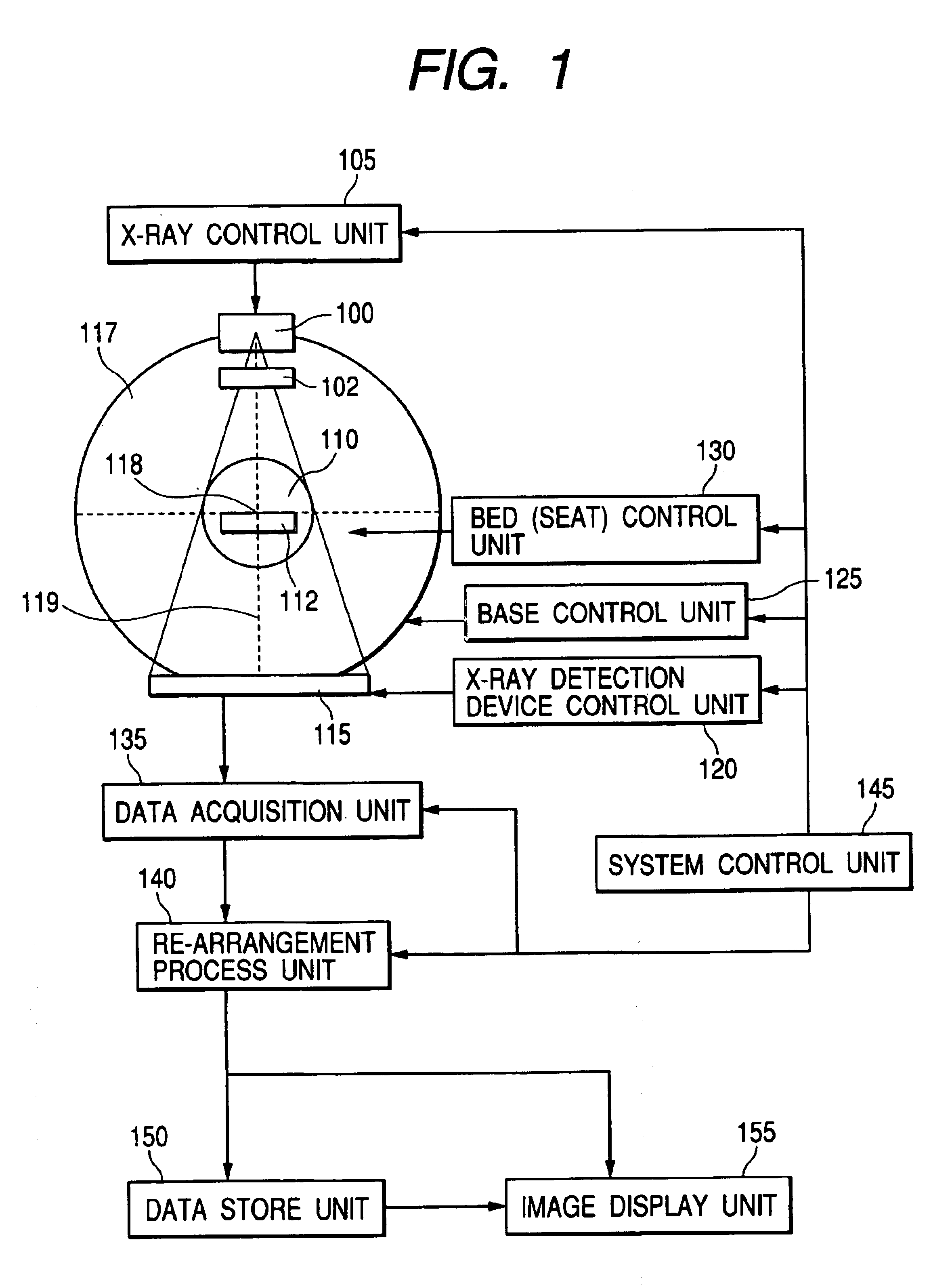
FIG. 1 is a schematic structural diagram showing a preferred example of an X-ray computed tomography apparatus according to this embodiment. In FIG. 1, reference numeral 100 denotes an X-ray source for projecting X-ray onto the object, 102 denotes an X-ray aperture for restricting projection area of X-ray, 105 denotes an X-ray control unit, 110 denotes an image taking region in which it is possible to rearrange an image, 112 denotes a bed (seat) for supporting the object, 115 denotes an X-ray detection device, 117 denotes a base for supporting the X-ray source 100 and the X-ray detection device 115, 118 denotes a rotation axis of rotational movement of the base 117, 119 denotes a central li...


PUM


Abstract

In order to remove a scattered line component resulting from an object from projection data to obtain a satisfactory rearrangement image, an amount of scattered line is calculated from a region in which a first-order X-ray is shielded by an X-ray shield and a component corresponding to the scattered line is removed. Then, an image in the region in which the first-order X-ray is shielded is complemented based on an image taken from a 180-degree opposite direction.

Description

BACKGROUND OF THE INVENTION1. Field of the InventionThe present invention relates to an X-ray computed tomography apparatus having an X-ray shield, and more particularly to a removal of a scattered line by detecting an amount of the scattered line from a region in which a first-order X-ray is shielded by the X-ray shield in a state in which the X-ray shield is located between a focal point of an X-ray source and an X-ray detection device.2. Related Background ArtIn recent years, an X-ray sensor capable of directly converting an X-ray image into a digital output in real time has been proposed. For example, it is possible to manufacture a solid light detection device in which solid light detection elements, each of which is composed of a transparent conductive film and a conductive film, are arranged in two-dimensional matrix on a substrate made of quartz glass with an amorphous semiconductor film interposed therebetween. Thus, the X-ray sensor is an X-ray detection device in which th...

Claims


Application Information

Patent Timeline
IPC IPC(8): G21K1/02A61B6/03A61B6/06
CPCG21K1/025A61B6/5282
Inventor NOKITA, MAKOTO
Owner CANON KK
Why Eureka
Try Eureka