Vibration-damped structure

a technology of vibration-damped structure and vibration-damped walls, which is applied in the direction of shock absorbers, bridges, building repairs, etc., can solve the problems of difficult application of existing structures, inability to install new walls, and restricted degree of installation freedom, so as to reduce the working man-hour, reduce the cost, and compact the effect of joining structur

Inactive Publication Date: 2005-01-11
OILES CORP
View PDF22 Cites 15 Cited by
  • Summary
  • Abstract
  • Description
  • Claims
  • Application Information

AI Technical Summary

Benefits of technology

According to this lower connecting means, since the narrow side wall of the box member and the lower-side-end flange plate are connected by means of the lower-side-end inner and outer splicing plates which are jointly fastened together with them, the connection is that based on two-plane friction type connection. Hence, it is possible to obtain a firm joint between the narrow side wall of the box member and the lower-side-end flange plate, so that the box member can be firmly joined to the lower girder side. Thus, even if large horizontal force and bending moment are applied to the box member and the resistance plate in the relative horizontal displacement between the box member and the resistance plate at the time of an earthquake or the like, it is possible to sufficiently withstand the shearing force and tensile force based on them. In other words, according to vibration-damped structure having the above-described vibration-damped columns, even if the number of the high-strength bolts is halved to effect the joining of the box member to the lower girder side through the two-plane friction type connection, it is possible to realize firm fixation equivalent to the one-plane friction type connection. Therefore, it is possible to attain a substantial decrease in the working man-hour and a reduction in cost and obtain a compact joining structure. Consequently, on a given floor, it is possible to enlarge the installation space for each of the box member and the resistance plate and use a large box member and a large resistance plate, thereby making it possible to enhance the vibration damping performance further.
In the vibration-damped structure having the vibration-damped columns using the rising plate, at least one of the lower-side-end inner splicing plate and the lower-side-end outer splicing plate may be formed of a high-friction steel plate whose high-friction surface is in contact with the narrow side wall plate and the lower-side-end flange plate, so as to efficiently and desirably secure the withstanding force against the horizontal force and the bending moment. In addition, the lower connecting means may be formed by further including a lower horizontal flange plate superposed on the bottom wall plate of the box member and secured to an upper edge of the rising plate; and high-strength bolts for fastening together the bottom wall plate and the lower horizontal flange plate.
In the case where the lower connecting means is formed by using the lower-side-end inner and outer splicing plates, an auxiliary plate whose one end is secured to the lower-side-end inner splicing plate and which extends alongside an upper surface of the bottom wall plate may be fixed to the bottom wall plate by means of a bolt. By using such an auxiliary plate, in the operation of installing the lower-side-end inner splicing plate, the auxiliary plate can be used like a temporarily fixing jig for the lower-side-end inner splicing plate. Thus, the operation of installing the lower-side-end inner splicing plate can be effected very easily, and the joint with the narrow side wall plate and the wide side wall plate can be effectively restrained by the auxiliary plate such that antiplane deformation will not occur at the joint. Accordingly, it is possible to prevent localized buckling and secure sufficient withstanding force for the joints.
To minimize the amount of projection of the lower-side-end inner splicing plate in the direction of the wall thickness and make it possible to use the wide lower-side-end inner splicing plate, as well as to more effectively obtain the two-plane friction type connection using the lower-side-end inner splicing plate, notches may be respectively formed in the bottom wall plate in a vicinity of one surface of the narrow side wall and in the lower horizontal flange plate in a vicinity of one surface of the lower-side-end flange plate, and the lower-side-end inner splicing plate may be arranged to extend vertically through the notches.

Problems solved by technology

However, since such vibration dampers are, in many cases, disposed between the structure and the ground, the vibration dampers have a problem in that they are difficult to be applied to existing structures.
However, with such vibration isolating walls, regardless of whether the structure is newly constructed or is an existing one, in a case where a necessary number of walls for obtaining the vibration damping effect in application are not present, there arises a need to install new walls within the structure to partition the interior of the structure into small units.
In addition, in places which are to be used as passages for connecting together rooms of the structure, the new walls cannot be installed.
In this respect, the degree of freedom of installation is restricted.
Hence, the space for installing the box member and the resistance plate is substantially restricted, and the size of the rooms of the structure is limited.
In particular, since tensile and compressive forces based on the bending moment are particularly concentrated on lateral end portions of the box member and the resistance plate, unless their strength is sufficient, there is the possibility of occurrence of localized buckling there.
From the viewpoint of preventing this localized buckling as well, the connecting structure becomes large, and the space for installing the box member and the resistance plate which demonstrate the damping performance becomes limited.
In addition, since the area of the resistance plate becomes small, the capability of the vibration damper declines, and there is a possibility that the rooms of the structure are made small due to the jutting out of the large connecting structure in antiplane directions.

Method used


Image

  • Vibration-damped structure
  • Vibration-damped structure
  • Vibration-damped structure

Examples


Embodiment Construction

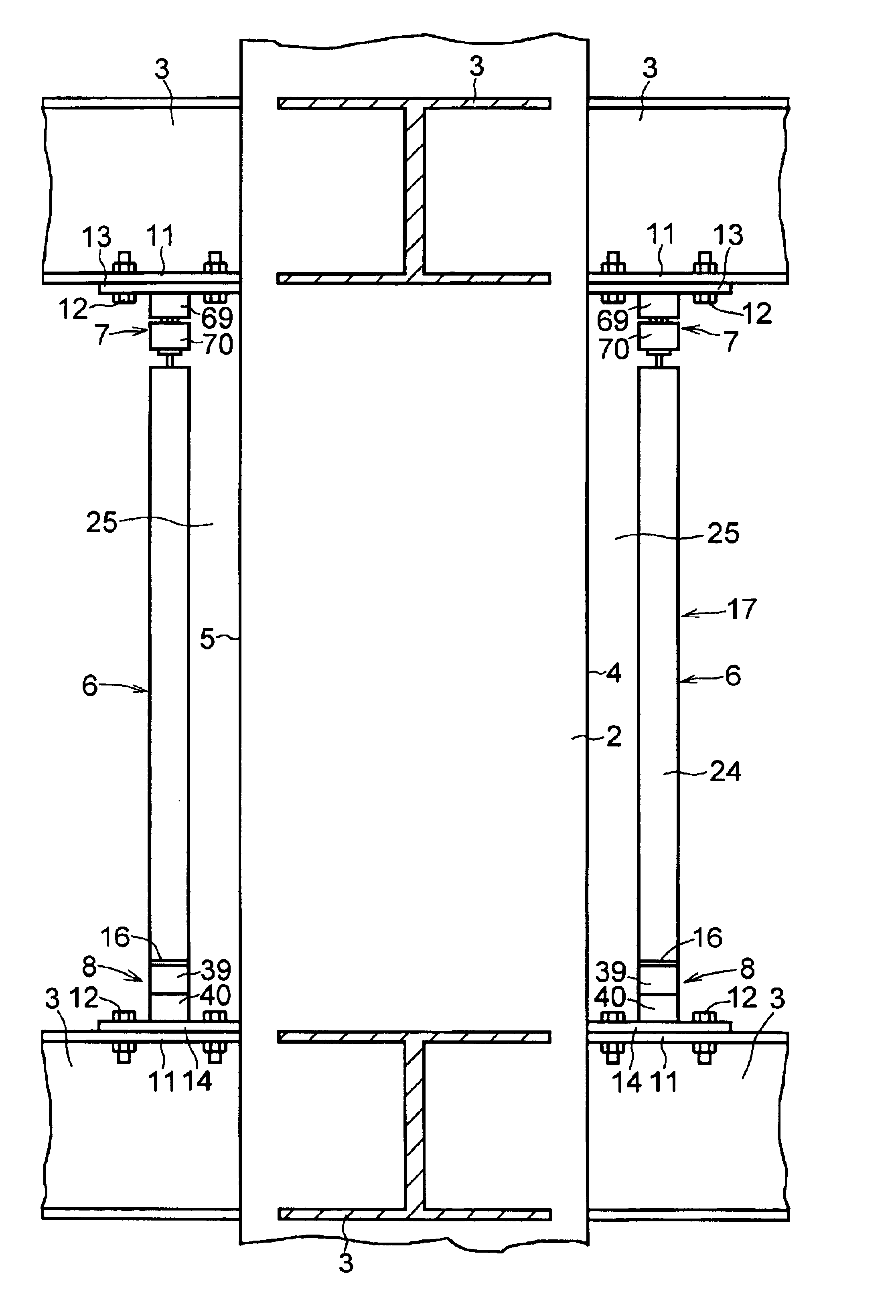
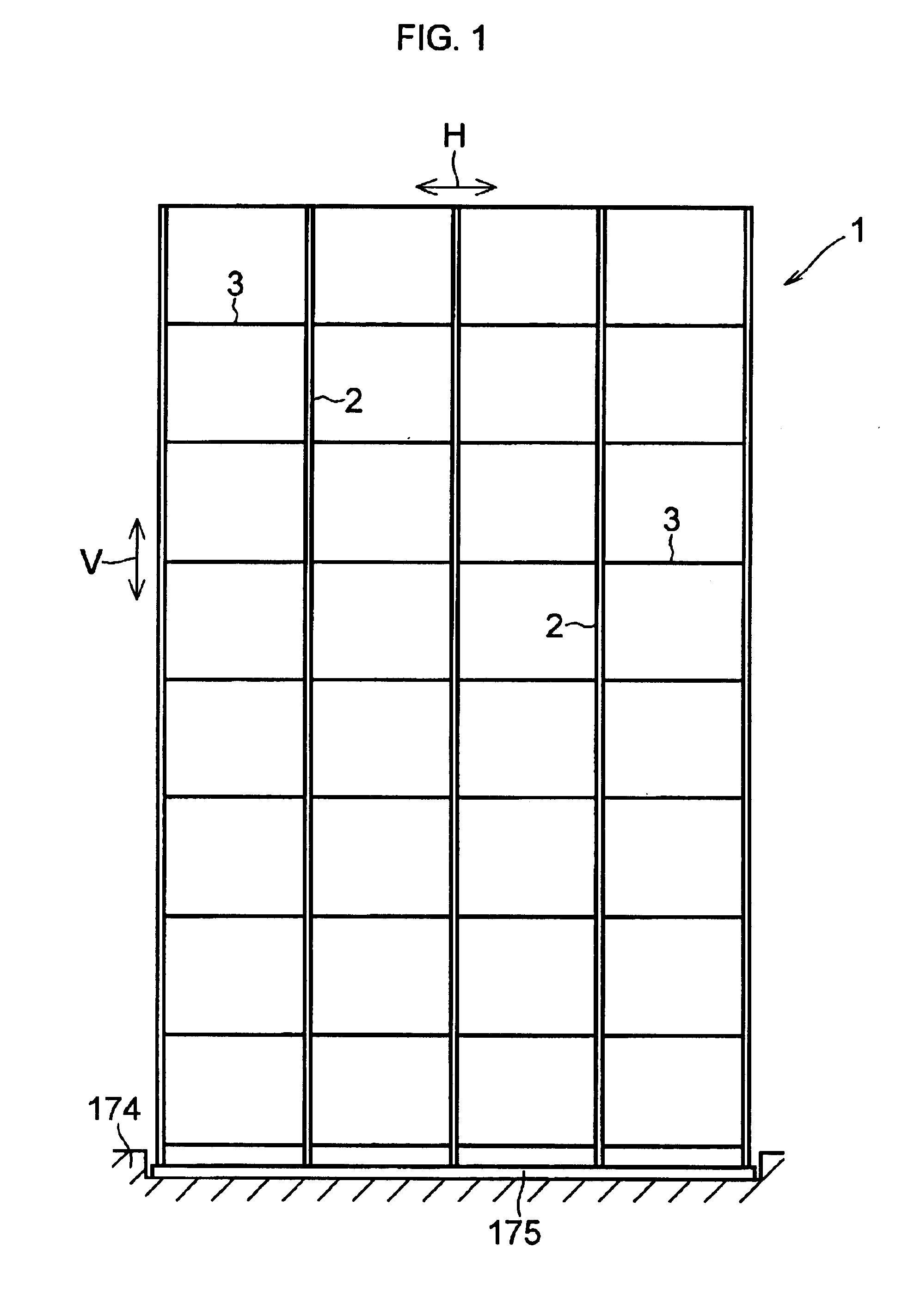
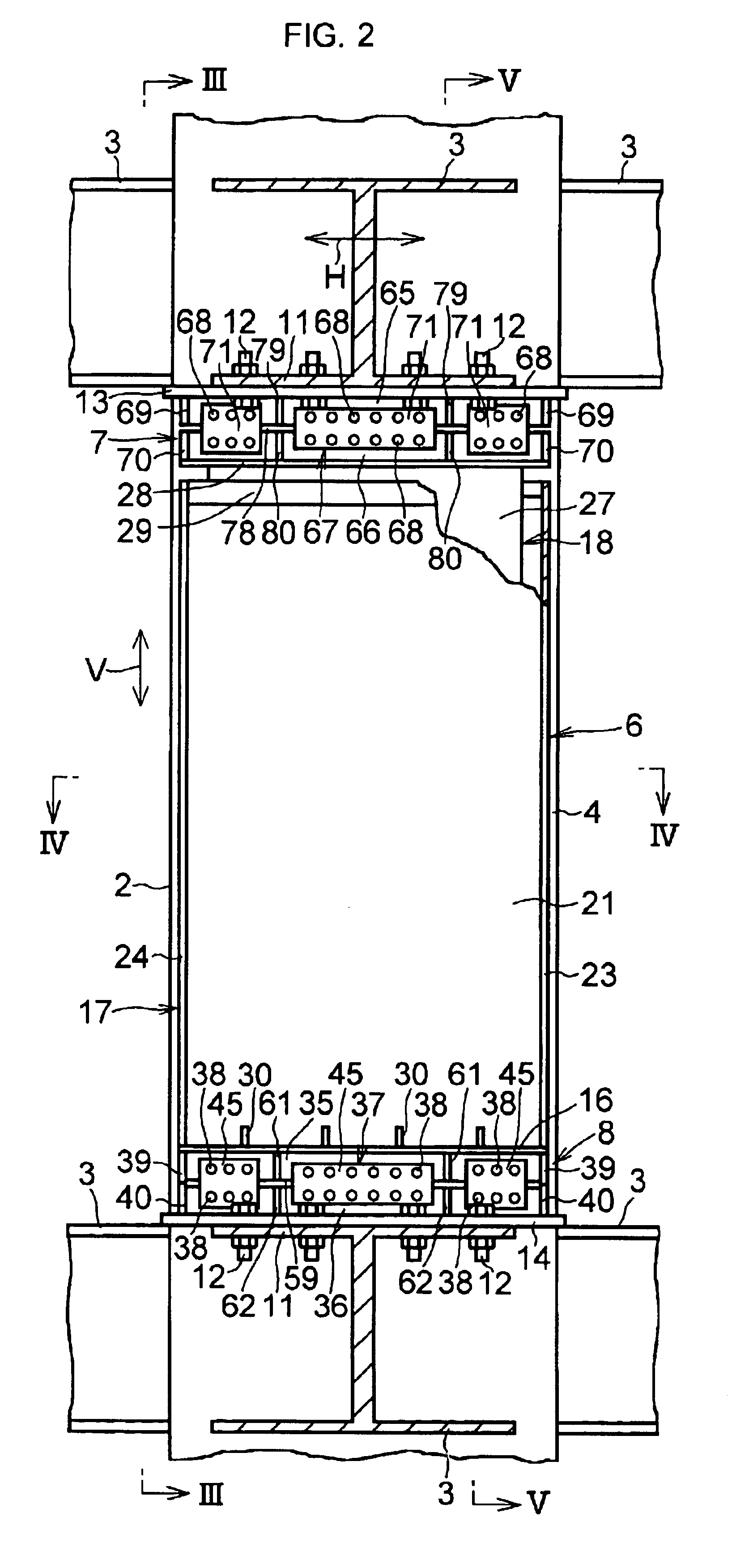
In FIGS. 1 to 7, a high-rise building 1 serving as a vibration-damped structure in accordance with this embodiment is comprised of a plurality of quadrangular columns (square columns) 2 disposed in such a manner as to extend in a vertical direction V so as to support the vertical load of the building 1; a plurality of girders 3 disposed in such a manner as to extend horizontally between the respective square columns 2 so as to bridge the respective square columns 2; two vibration damping means 6 juxtaposed to opposing side surfaces 4 and 5 of each square column 2 on a predetermined floor, e.g., each floor, of the building 1; and upper and lower connecting means 7 and 8 for connecting the respective vibration damping means 6 to the respective ceiling- and floor-side girders 3 on each floor.

Each square column 2 is made of reinforced or steel framed concrete and supports respective one end portions of the girders 3.

At one end portion of each girder 3 formed of H shape steel, mounting p...


PUM


Abstract

A building (1) includes square columns (2) disposed in such a manner as to extend in a vertical direction so as to support the vertical load of the building (1); girders (3) disposed in such a manner as to bridge the square columns (2) and extend in the horizontal direction between the square columns (2); variation damping means (6) juxtaposed to opposing side surfaces (4) and (5) of each square column (2) on each floor of the building (1); and upper and lower connecting means (7) and (8) for connecting the vibration damping means (6) to a ceiling girder (3) side and a floor girder (3) side, respectively.

Description

TECHNICAL FIELDThe present invention relates to a vibration-damped structure in which the lateral (horizontal) deformation and vibration of columns supporting the vertical load of a structure such as a building due to an earthquake, winds, traffic vibrations, and the like are decreased as quickly as possible, and the vibration of the structure is thereby damped.BACKGROUND ARTTo damp as quickly as possible the lateral (horizontal) vibration of a structure such as a building for businesses or offices, a multiple dwelling house, and a detached house, which serve as buildings, as well as a bridge, an abutment, and the like due to an earthquake, winds, traffic vibrations, and the like, vibration dampers such as lead dampers, viscous dampers, steel rod dampers, and the like are used. However, since such vibration dampers are, in many cases, disposed between the structure and the ground, the vibration dampers have a problem in that they are difficult to be applied to existing structures.On...

Claims


Application Information

Patent Timeline
Patent Type & Authority Patents(United States)
IPC IPC(8): E04H9/02F16F15/023F16F7/08F16F9/10F16F7/00E01D1/00E04G23/02
CPCE04H9/02F16F15/023F16F9/10F16F7/08E04H9/028E04H9/0235E04H9/0237E04H9/024F16F2230/0023E04H9/0215
Inventor SHIMODA, IKUOSUZUKI, KIYOHARU
Owner OILES CORP
Why Eureka
Try Eureka