Evaporator, a heat absorber, a thermal transport system and a thermal transport method

a technology of evaporator and heat absorber, which is applied in the direction of indirect heat exchangers, lighting and heating apparatus, and separation processes. it can solve the problems of large and heavyweight configuration, difficult pressure control within the loop, and difficulty in equalizing the liquid supply of each evaporator

Inactive Publication Date: 2005-01-11
MITSUBISHI ELECTRIC CORP
View PDF18 Cites 76 Cited by
  • Summary
  • Abstract
  • Description
  • Claims
  • Application Information

AI Technical Summary

Problems solved by technology

However, the parallel connection has disadvantages that: 1) liquid-phase working fluid in each evaporator dries out quickly, because it is difficult to equalize a liquid supply to each evaporator; and 2) pressure control within a loop is difficult.
However such additional components caused complicated, large and heavyweight configuration and high manufacturing cost.
As mentioned above, as the parallel connection of the evaporators 1 need

Method used


Image

  • Evaporator, a heat absorber, a thermal transport system and a thermal transport method
  • Evaporator, a heat absorber, a thermal transport system and a thermal transport method
  • Evaporator, a heat absorber, a thermal transport system and a thermal transport method

Examples


embodiment 4

This embodiment shows an application of the thermal transport system of the present invention for cooling of a motor.

FIG. 8A is a front view of the motor installing the evaporators 1. FIG. 8B is a side view.

In the figures, 30 is the motor, 31 is a motor casing, 1,5, and 9 are same as those in the embodiment 1.

The evaporators 1 inserted into the motor casing are connected to each other via the liquid flow line 9.

Since the evaporator of the last position is connected to the reservoir tank 10 not shown in FIGS. 8A and 8B, it is possible to adjust the amount of the liquid in the liquid reservoir of each evaporator.

The vapor line of each evaporator extending from one end of the motor to the other end of the motor transfers the vapor to the condenser 7 as indicated by an arrow.

embodiment 5

This embodiment shows an application of the thermal transport system of the present invention for cooling of an artificial satellite.

FIGS. 9A and 9B show schematic views of the artificial satellite installing the thermal transport system.

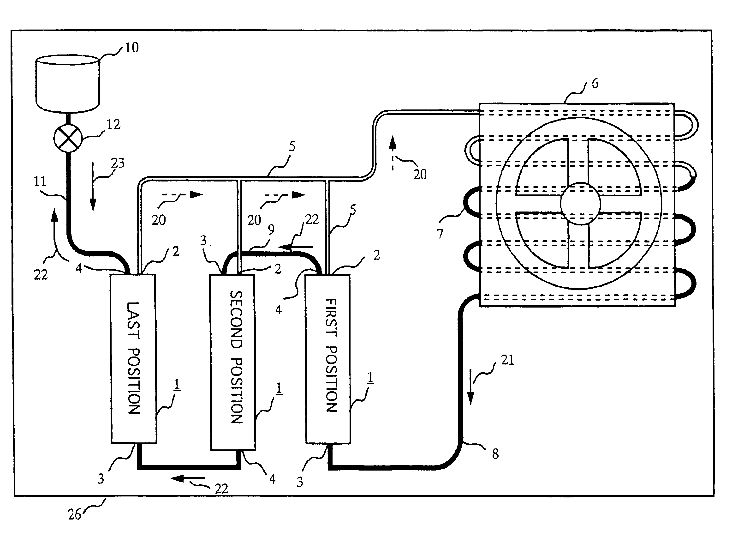
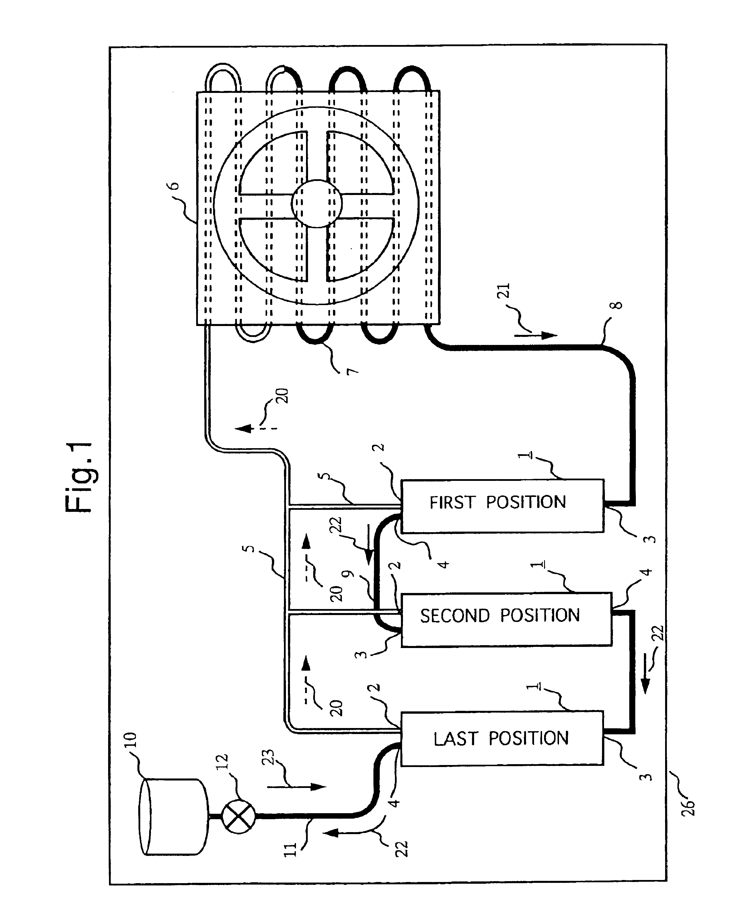
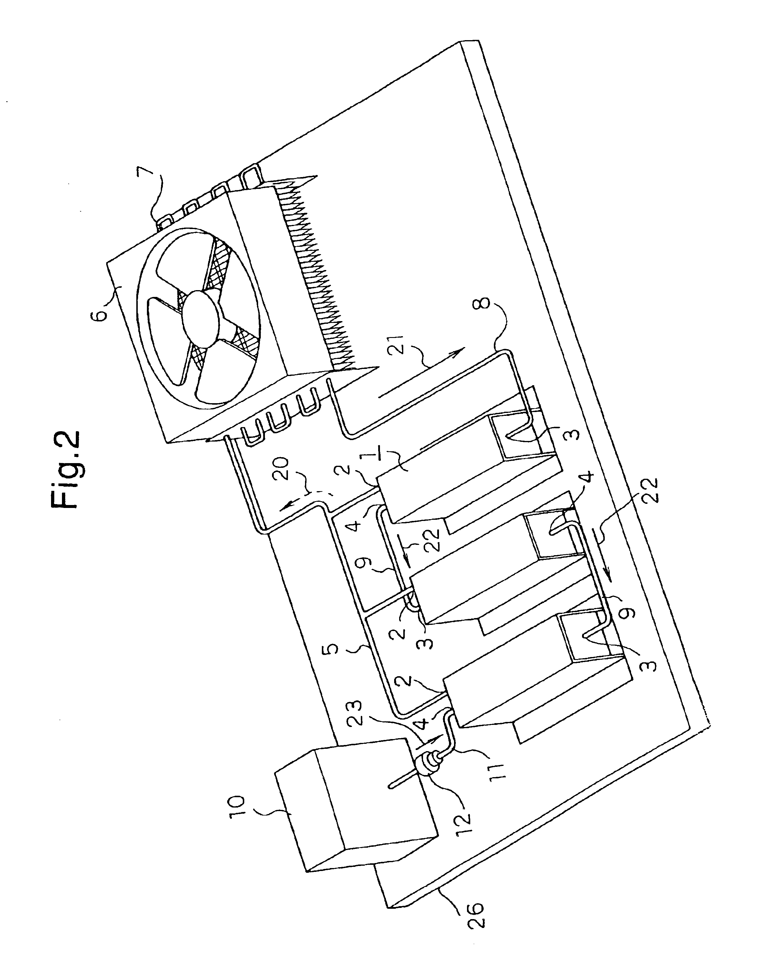
Components 1,5,7,8,9,11,19,20,21, and 22 are same as those in the embodiment 1.

Components 10a,10b, and 10c are same as those in the embodiment 2.

In FIG. 9B, 32 stands for a chassis of the artificial satellite.

The system in this embodiment is to radiate the heat by placing evaporators 1 on the wall which faces the sun and is heated by the sun as indicated by the arrow 19, and placing the condenser 7 on the wall being in the shade.

The structure and the function of the system are same as those in the embodiment 1.

FIG. 9B illustrates the evaporators 1 on a bottom wall and the condenser 7 on a front wall, however in a practical application the evaporators 1 are both on the upper and bottom walls, and the condensers 7 are both on the front and back walls,...

embodiment 6

FIG. 10 shows a schematic view of an application of the thermal transport system of the present invention for cooling of a computer.

In FIG. 10, 33 is a chassis of the computer. Components 1,5,7,8,9,11,19,20,21, and 22 are same as those in the embodiment

In cases of multi-processor consisting of a plurality of CPUs (Central Processing Unit), it is necessary to place each evaporator above each CPU, and it is possible to apply the thermal transport system of the invention.

A demand to downsize the personal computers especially are strong, such that the system of the present invention is useful in reducing the size and weight of personal computers.

The structure and the function are same as those described in the embodiment 1.


PUM


Abstract

The conventional thermal transport system has disadvantages of the configuration being complex, large, heavyweight and expensive. In the present invention, a plurality of evaporators are connected in series via the liquid flow line, the evaporator of the first position is connected to the condenser via the liquid supply line, the evaporator of the last position is connected to the reservoir tanks for adjusting the amount of the liquid. The liquid amount measuring sensor is installed to measure the amount of the liquid in the liquid reservoir of the evaporator. Based on the measured result of the liquid amount measuring sensor, the control valve operates so as to supply the liquid accommodated in the reservoir tanks to each evaporator.

Description

BACKGROUND OF THE INVENTION1. Field of the InventionThe present invention relates to an evaporator, a heat absorber and a thermal transport system.2. Description of the Related ArtThermal transport systems such as CPL (Capillary Pumped Loop) and LHP (Looped Heat Pipe) are commonly used in various applications like spacecraft, industrial machinery and home apparatus.Since an evaporator of these thermal transport systems has a very narrow and thin structure therefore multi-connection of the evaporators is required to cover a wide range of heat generation area or distributed heat generation areas.In this respect, previously, a parallel connection of CPL evaporators is adopted as shown in FIG. 11.However, the parallel connection has disadvantages that: 1) liquid-phase working fluid in each evaporator dries out quickly, because it is difficult to equalize a liquid supply to each evaporator; and 2) pressure control within a loop is difficult.Therefore, a conventional system is supported b...

Claims


Application Information

Patent Timeline
IPC IPC(8): B01D3/00F25B23/00F28D15/02F28D15/06
CPCB01D3/007F28D15/0266F25B23/006
Inventor KOBAYASHI, TAKASHIOGUSHI, TETSUROTSUJIMORI, ATSUSHIKAMOYA, YOSHIHIRO
Owner MITSUBISHI ELECTRIC CORP
Why Eureka
Try Eureka