Thermal management system and associated method

a technology of thermal management system and thermal management system, applied in the direction of electrical apparatus construction details, transportation and packaging, synthetic resin layered products, etc., can solve the problems of reducing the thermodynamic driving force for heat removal, generating heat that may need to be dissipated by the electronic device during operation, etc., to achieve improved thermal transport performance and higher thermal conductivity

Inactive Publication Date: 2007-10-18
GENERAL ELECTRIC CO
View PDF11 Cites 15 Cited by
  • Summary
  • Abstract
  • Description
  • Claims
  • Application Information

AI Technical Summary

Benefits of technology

[0008] It may be desirable to obtain a structure and/or method for thermal transport than might not otherwise be available. It may be desirable to obtain a structure and/or method for thermal transport having rela

Problems solved by technology

Some electronic devices generate heat during operation that may need to be dissipated.
The operating temperature requirement may reduce the temperat

Method used


Image

  • Thermal management system and associated method
  • Thermal management system and associated method
  • Thermal management system and associated method

Examples


example 1

In-Situ Thermal Characterization of Thermal Transport Structure

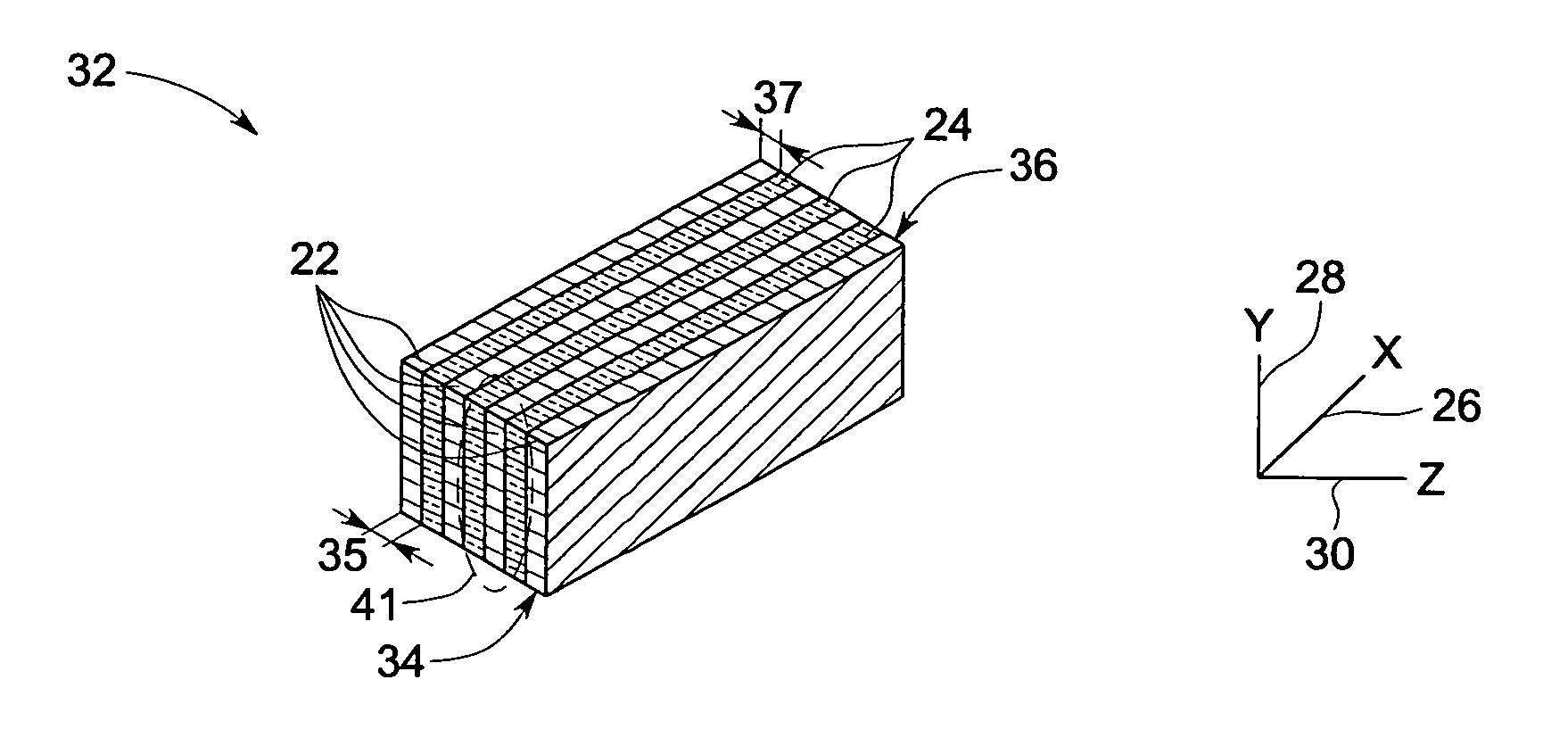
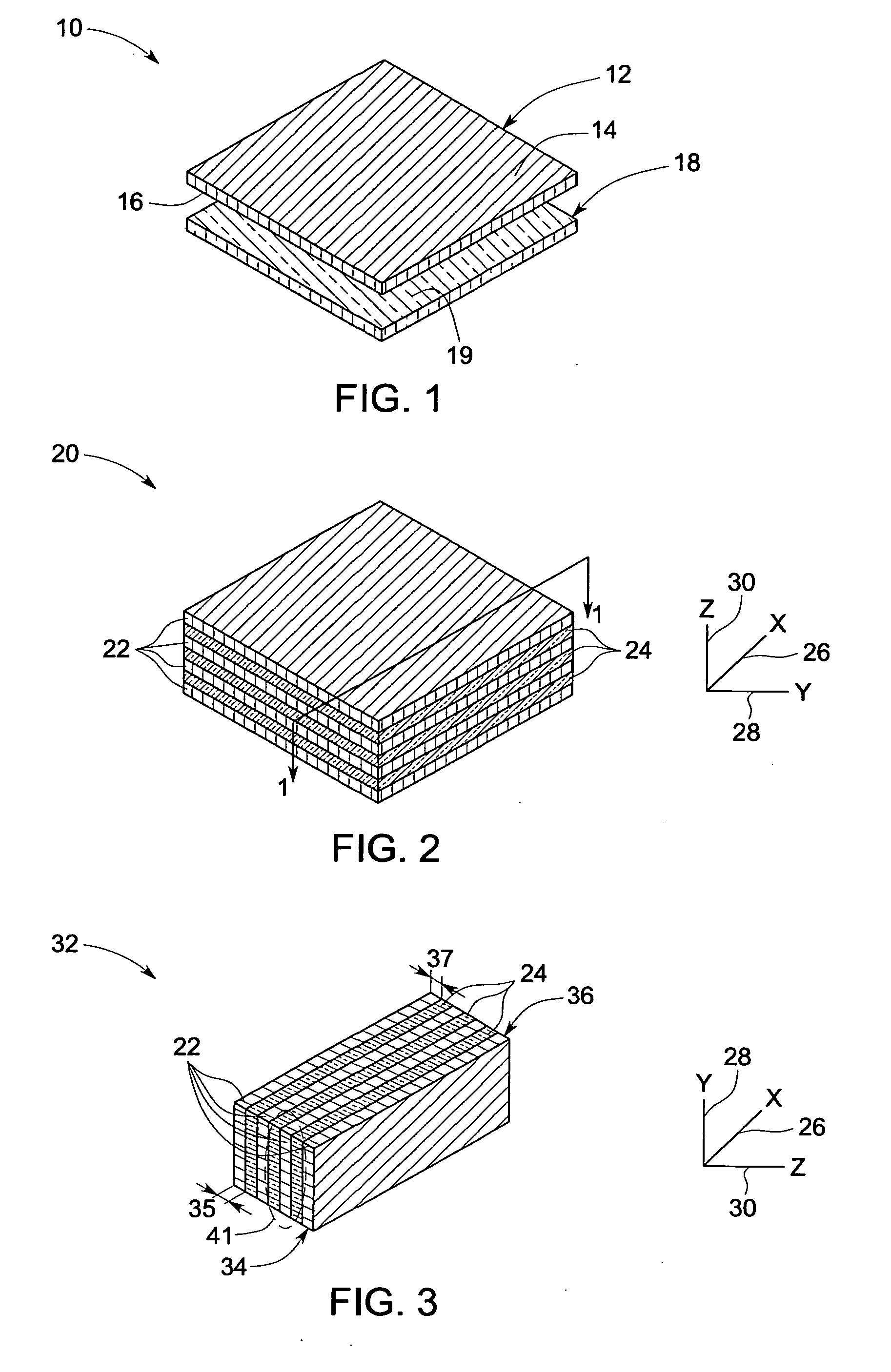
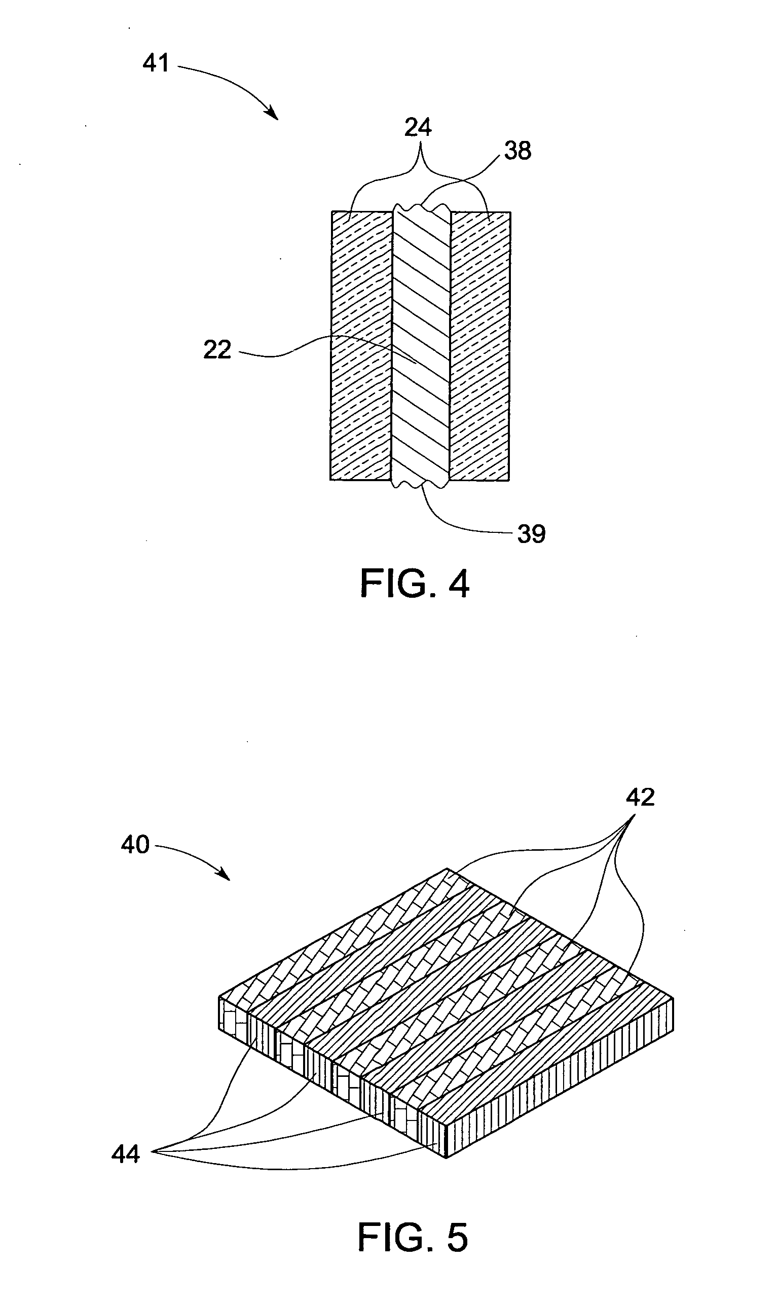
[0107] A resin layer is sprayed onto a sacrificial film. The resin layer is a mixture of an epoxy, RSL 1739 available from Hexion Specialty Chemicals (Houston, Tex.), and a hardener, hexahydro-4-methylphthalic anhydride available from Sigma-Aldrich (St. Louis, Mo.). The resin layer also includes a catalyst, Polycat SA-1 available from Air Products (Allentown, Pa.). Heat from a heat lamp at least partially cures the resin layer after spraying to form a film. Thermal pyrolytic graphite (TPG) bars are commercially available from GE Advanced Ceramics (Strongsville, Ohio) having dimension of 100 milimeters×100 milimeters and a thickness of about 2 milimeters are aligned on the resin layer. The thermal pyrolytic graphite (TPG) bars are aligned and areorientation such that the plane having the highest thermal conductivity is placed parallel to the sacrificial film. The process is repeated to form a stack having alternate layer...

example 2

Effect of Thickness of Thermal Transport Layer on Interfacial Thermal Resistance

[0114] In Example 2, thermal transport structures (TTS) are prepared in the same manner as in Example 1, except that the thickness of the thermal transport layer differs from sample to sample. Samples 5-7 have thickness of 490, 500, and 100 respectively.

[0115] Aligning each of the thermal transport structures between two substrates makes a test coupon. The plane of the TTS having the highest thermal conductivity is placed perpendicular to the substrates. The first substrate is an aluminum substrate having a density of 2.63 g / cm3, heat capacity of 0.861 J / g-K, and a thermal conductivity of 130 W / m-K. The second substrate is a silicon substrate having a density of 2.33 g / cm3, heat capacity of 0.70 J / g-K, and a thermal conductivity of 135 W / m-K.

[0116] The experimental set up 102 is illustrated in FIG. 17. As with the set up 82 of FIG. 16, the set up 102 may include clamps 104 and 106. The TTS 108 is inte...


PUM

PropertyMeasurementUnit
Timeaaaaaaaaaa
Timeaaaaaaaaaa
Timeaaaaaaaaaa

Abstract

A method for making a thermal interface structure is provided. The method may include disposing a thermal transport layer on a resin layer to form a stacked structure, and slicing the stacked structure to form a cross-sectional slice having a first exposed portion of the thermal transport layer on a first surface of the slice, and a second exposed portion of the thermal transport layer on the second surface of the slice.

Description

STATEMENT REGARDING FEDERALLY SPONSORED RESEARCH & DEVELOPMENT [0001] This invention was made with Government support under contract number 70NANB2H3034 awarded by U.S. National institute of Standards and Technology. The Government may have certain rights in the invention.BACKGROUND [0002] 1. Technical Field [0003] The invention includes embodiments that may relate to a thermal transport structure. The invention includes embodiments that may relate to a method of making and / or using the thermal transport structure. [0004] 2. Discussion of Related Art [0005] Some electronic devices generate heat during operation that may need to be dissipated. As electronic devices become denser and more highly integrated, the heat flux requirement may increase. Because of performance and reliability considerations, the devices may need to operate at lower temperatures. The operating temperature requirement may reduce the temperature difference between the heat-generating device and the ambient tempe...

Claims


Application Information

Patent Timeline
IPC IPC(8): B21D53/02B32B7/027
CPCB32B27/06Y10T29/49366B32B5/14B32B7/02B32B27/08B32B27/20B32B2264/102B32B2264/105B32B2307/30B32B2307/302B32B2307/706Y10T428/269Y10T29/49885Y10T29/4935H05K7/20481B32B7/027
Inventor ZHANG, JIANTONAPI, SANDEEP SHRIKANTMILLS, RYAN CHRISTOPHERGOWDA, ARUN VIRUPAKSHA
Owner GENERAL ELECTRIC CO
Why Eureka
Try Eureka