Heat transport structure and manufacturing method thereof

a transport structure and heat transport technology, applied in the direction of lighting and heating apparatus, semiconductor/solid-state device details, laminated elements, etc., can solve the problems of increasing the amount of heat generated by electronic devices, increasing the weight of metal materials, and insufficient flexibility of metal materials, etc., to achieve good heat dissipation properties, and good light weight

Active Publication Date: 2017-12-28
KANEKA CORP
View PDF2 Cites 15 Cited by
  • Summary
  • Abstract
  • Description
  • Claims
  • Application Information

AI Technical Summary

Benefits of technology

[0047]An embodiment of the present invention (first invention) makes it possible to provide a thermal transport structure having good bendability, a good heat dissipation property, and a good lightweight property.
[0048]An embodiment of the present invention (second invention) makes it possible to provide a thermal transport structure having a high reliability against vibrations and an excellent heat transport performance.

Problems solved by technology

However, in recent years, the amount of heat which electronic devices generate has been increasing.
This has been leading to insufficient flexibility of the metal material.
Meanwhile, an increase in weight of the metal material has been also a problem.
However, there has been a problem that bendability of a graphite composite material decreases in a case where graphite sheets are stacked via an adhesive or the like so as to form a layer stack as in Patent Literature 1.
On the other hand, in a case where graphite sheets are stacked via no bonding layer, a gap is produced between graphite sheets, so that a contact thermal resistance disadvantageously increases.
This has led to a problem that heat conductivity largely deteriorates at a part where heat from a heat source is received.
This has caused a problem that a required amount of a thermally conductive material to be used increases.
There has been a concern that such vibrations may cause a serious adverse effect to the electronic device.
Further, there has been also a concern that the vibrations may cause metal fatigue of a thermally conductive material and may consequently lead to a decrease in heat conductivity of the thermally conductive material.
In this way, reliability against vibrations has been low in a case where the metal material is used as a thermally conductive material.
The phrase “reliability against vibrations is low” means that vibrations largely damage an electronic device and consequently, heat conductivity of the thermally conductive material is likely to deteriorate.
Meanwhile, the phrase “reliability against vibrations is high” or “reliability against vibrations is sufficient” means that damage to an electronic device is small and accordingly, heat conductivity of the thermally conductive material is unlikely to deteriorate.
However, Patent Literature 1 does not disclose any thermal transport body capable of efficiently transporting heat.
Accordingly, it is difficult to use the structure as a thermal transport structure which can be freely bent or which can prevent reliability deterioration caused by vibrations.

Method used


Image

  • Heat transport structure and manufacturing method thereof
  • Heat transport structure and manufacturing method thereof
  • Heat transport structure and manufacturing method thereof

Examples


embodiment a

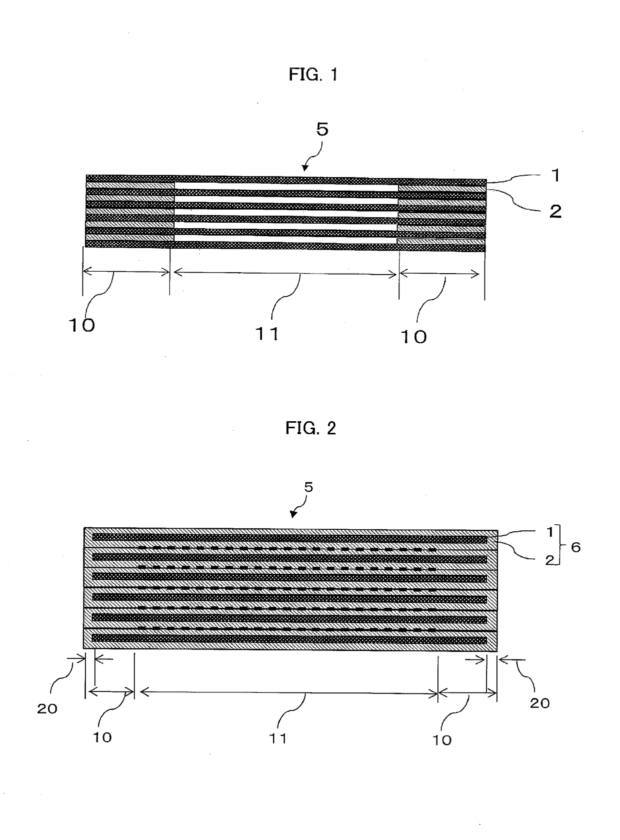
[0078]Embodiment A of the present invention is a thermal transport structure including at least two graphite sheets or at least two graphite composite sheets each including a graphite sheet and a covering layer, the covering layer covering at least part of (i) a surface and (ii) an edge (e.g., all faces including both surfaces and all edges) of the graphite sheet, the at least two graphite sheets or the at least two graphite composite sheets being stacked on top of each other as layers. The thermal transport structure includes: at least two fixing portions; and a thermally conductive portion between the fixing portions. In each of the fixing portions, the graphite sheets or the graphite composite sheets are kept in a state in which the graphite sheets or the graphite composite sheets are in contact with each other or bonded to each other (in other words, in each of the fixing portions, the graphite sheets or the graphite composite sheets are fixed in a state in which the graphite sh...

embodiment 1

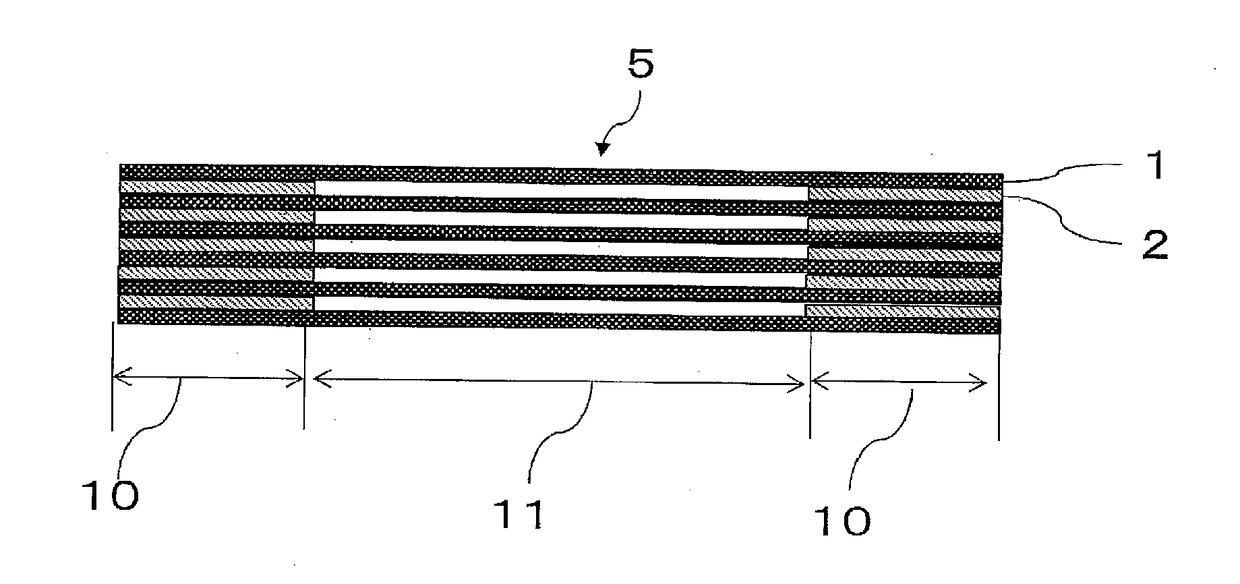
[0085]FIG. 1 is a cross sectional view schematically illustrating an example of a thermal transport structure in accordance with Embodiment 1 of the present invention. Embodiment 1 is a thermal transport structure 5 in which at least two graphite sheets 1 are stacked on top of each other as layers. The thermal transport structure 5 includes at least two fixing portions 10 and a thermally conductive portion 11. The fixing portions 10 are preferably provided at least at a heat-receiving position and a heat dissipating position, respectively. The thermally conductive portion 11 is provided between fixing portions 10. Further, in each of the fixing portions 10, a bonding layer 2 is provided between graphite sheets 1.

[0086](Fixing Portion)

[0087]The fixing portions in accordance with an embodiment of the present invention are each a portion where the graphite sheets of all layers are bonded to each other via a bonding layer when the graphite sheets are viewed in a direction in which the g...

embodiment 2

Production Methods of Embodiment 2

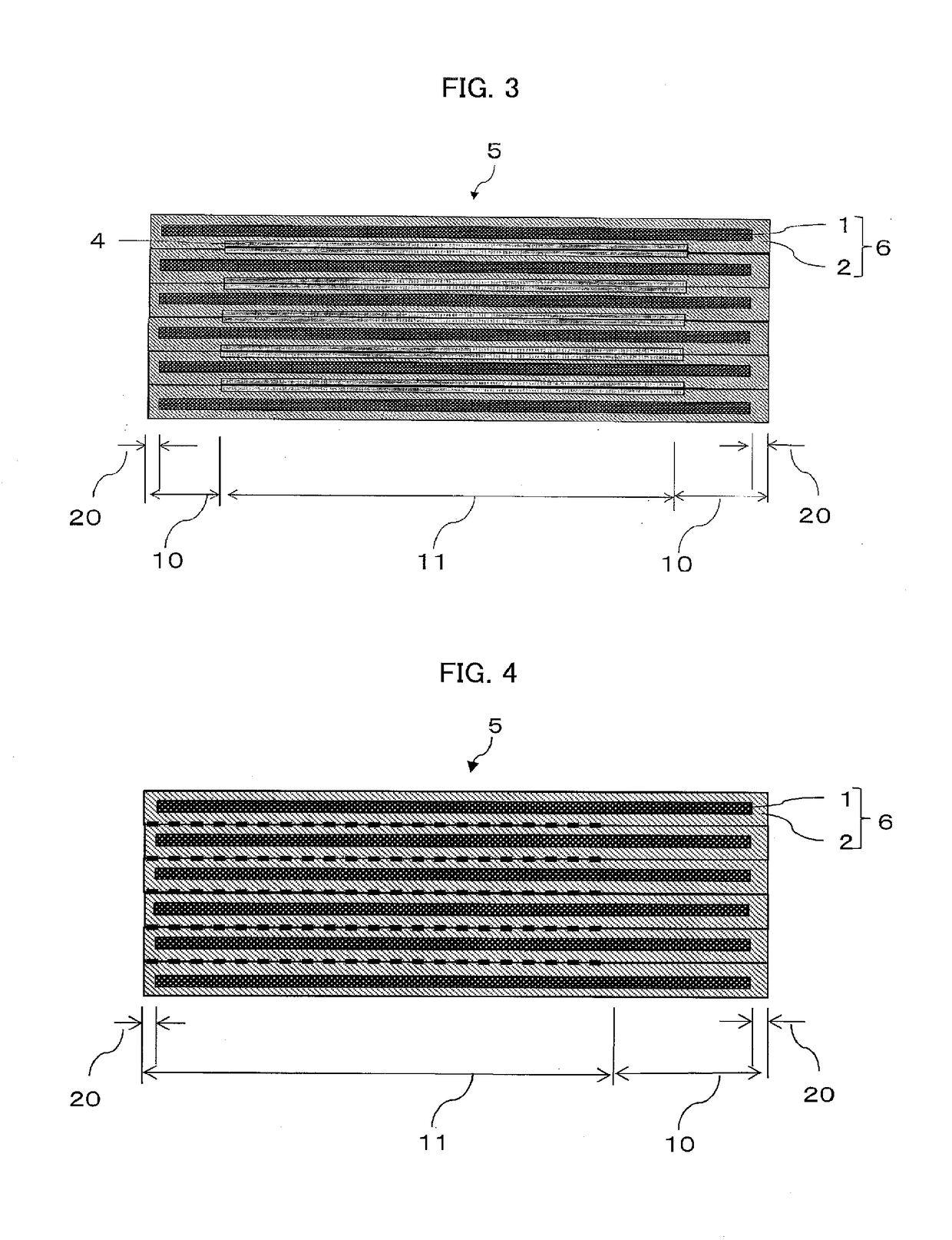
[0177]A method for producing a thermal transport structure of Embodiment 2 of the present invention involves: a step of preparing a graphite composite sheet by forming a bonding layer on the entire surfaces of a graphite sheet; and a step of stacking such graphite composite sheets on top of each other and thereafter bonding the sheets together by applying pressure or applying pressure and heat.

First Production Method of Embodiment 2

[0178]A first method for producing a thermal transport structure of Embodiment 2 of the present invention includes: a graphite composite sheet preparation step of preparing a graphite composite sheet by forming a bonding layer on the entire surfaces of a graphite sheet; and a bonding step performed after the graphite composite sheet preparation step. In the bonding step, graphite composite sheets and non-bonding layers are alternately stacked on top of each other to form a multilayer body and thereafter pressure is applie...


PUM

PropertyMeasurementUnit
thicknessaaaaaaaaaa
thicknessaaaaaaaaaa
thicknessaaaaaaaaaa

Abstract

In order to provide a thermal transport structure excellent in bendability, heat dissipation property, and lightweight property and also a thermal transport structure having a high reliability against vibrations and an excellent heat transport performance, used is a thermal transport structure (5, 201) including stacked graphite sheets (1, 213). This thermal transport structure (5, 201) includes a fixing portion (10, 202, 301) in which the stacked graphite sheets (1, 213) are fixed to each other;and a thermally conductive portion (11, 203) in which the stacked graphite sheets (1, 213) are not fixed to each other.

Description

TECHNICAL FIELD[0001]The present invention relates to a thermal transport structure and a method for producing the thermal transport structure.BACKGROUND ART[0002]There has been a demand for a thermally conductive material capable of transferring heat from a heat source to a cooling source or a thermally conductive material capable of being used in a bent state during transfer of heat from a heat source to a cooling source. This demand is intended to deal with complication of internal structures of electronic devices. As such a thermally conductive material, conventionally, a metal material (e.g., copper or aluminum) such as metal foil has been used.[0003]However, in recent years, the amount of heat which electronic devices generate has been increasing. Accordingly, a required thickness of a metal material has increased. This has been leading to insufficient flexibility of the metal material. Meanwhile, an increase in weight of the metal material has been also a problem. As a possib...

Claims


Application Information

Patent Timeline
Patent Type & Authority Applications(United States)
IPC IPC(8): B32B9/04C01B32/182C04B35/52F28F3/00H01L23/36H05K7/20
CPCB32B9/04C01B32/182H05K7/20F28F3/00H01L23/36C04B35/52B32B9/00H01L2924/0002B32B9/007B32B9/045B32B27/281B32B27/32B32B27/36C01B32/21H01L2924/00C01B32/20
Inventor KUTSUMIZU, MAKOTOOKU, SATOSHIKATO, YUSUKENISHIKAWA, YASUSHI
Owner KANEKA CORP
Why Eureka
Try Eureka