Gas cylinder

a gas cylinder and gas valve technology, applied in the field of gas cylinders, can solve the problems of high cost consumption, and achieve the effect of reducing the manufacturing cost of gas cylinders and maximizing the stroke distance of gas cylinders

Inactive Publication Date: 2005-01-11
SAMHONGSA
View PDF2 Cites 2 Cited by
  • Summary
  • Abstract
  • Description
  • Claims
  • Application Information

AI Technical Summary

Benefits of technology

According to the present invention, stroke distance of the gas cylinder could be maximized.
Also, manufacturing costs of the gas cylinder could be reduced.

Problems solved by technology

Also, as separate parts for use in manufacturing the gas cylinder should be newly made, much costs has been consumed.

Method used


Image

  • Gas cylinder
  • Gas cylinder
  • Gas cylinder

Examples


Embodiment Construction

The following detailed description will present a gas cylinder according to a preferred embodiment of the invention in reference to the accompanying drawings. The matters defined in the description such as a detailed construction are nothing but the ones provided to assist in a comprehensive understanding of the invention. Thus, it is apparent that the present invention can be carried out without those defined matters and it will be understood by those skilled in the art that various changes in form and details may be made therein without departing from the spirit and scope of the invention.

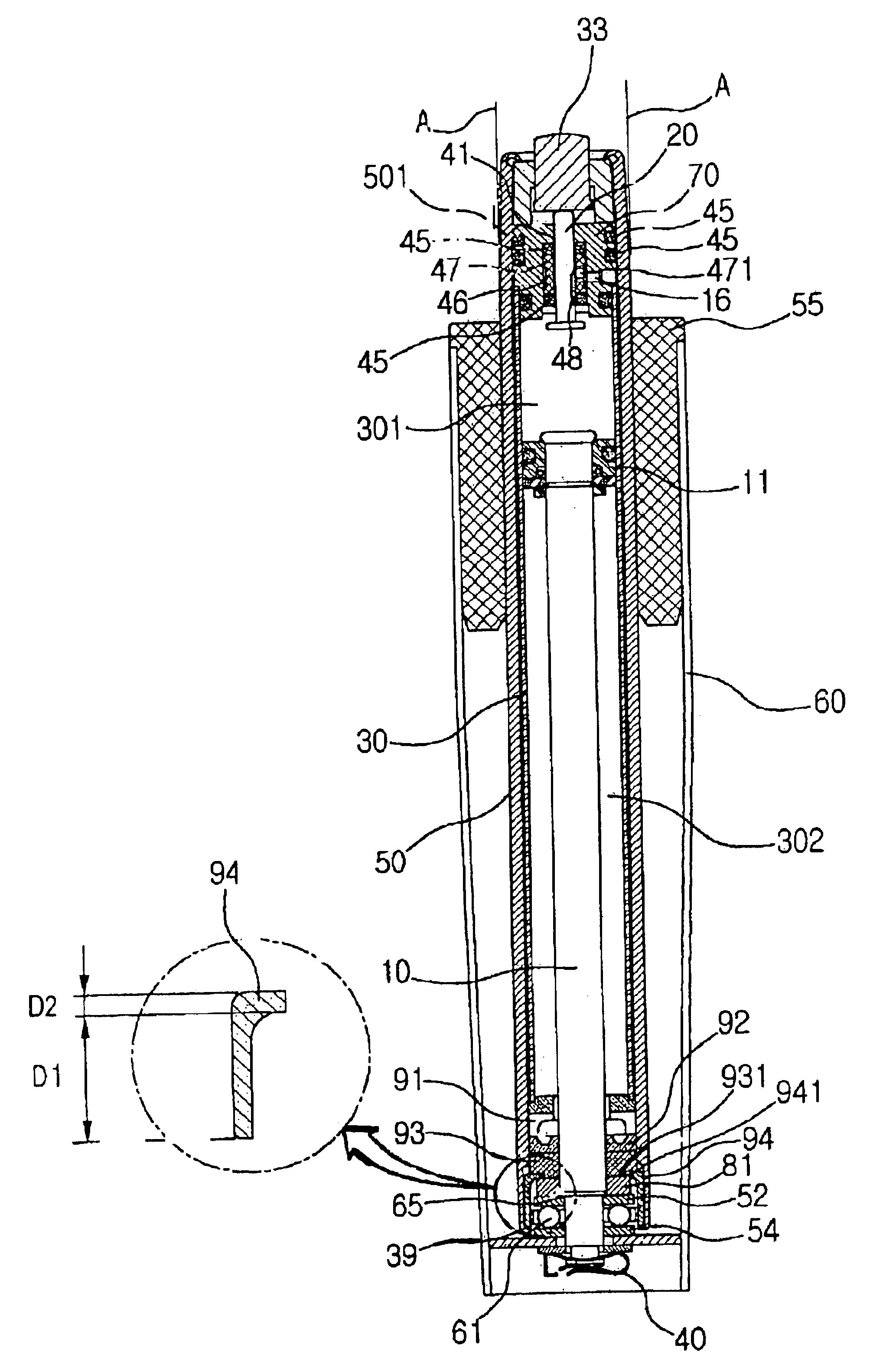
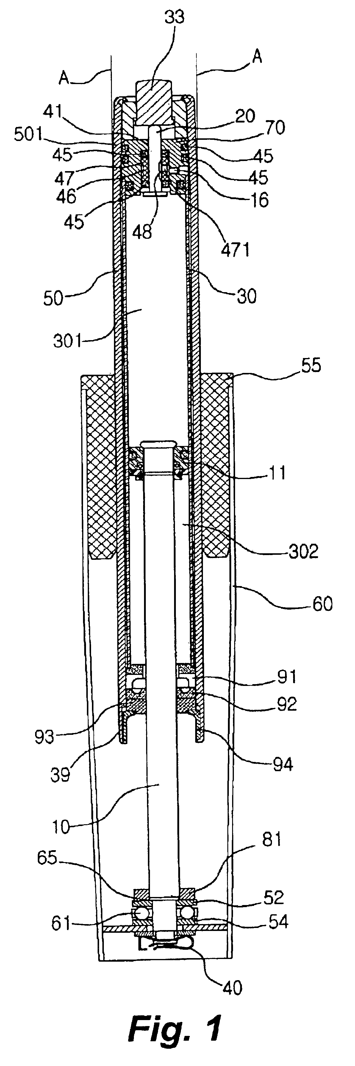
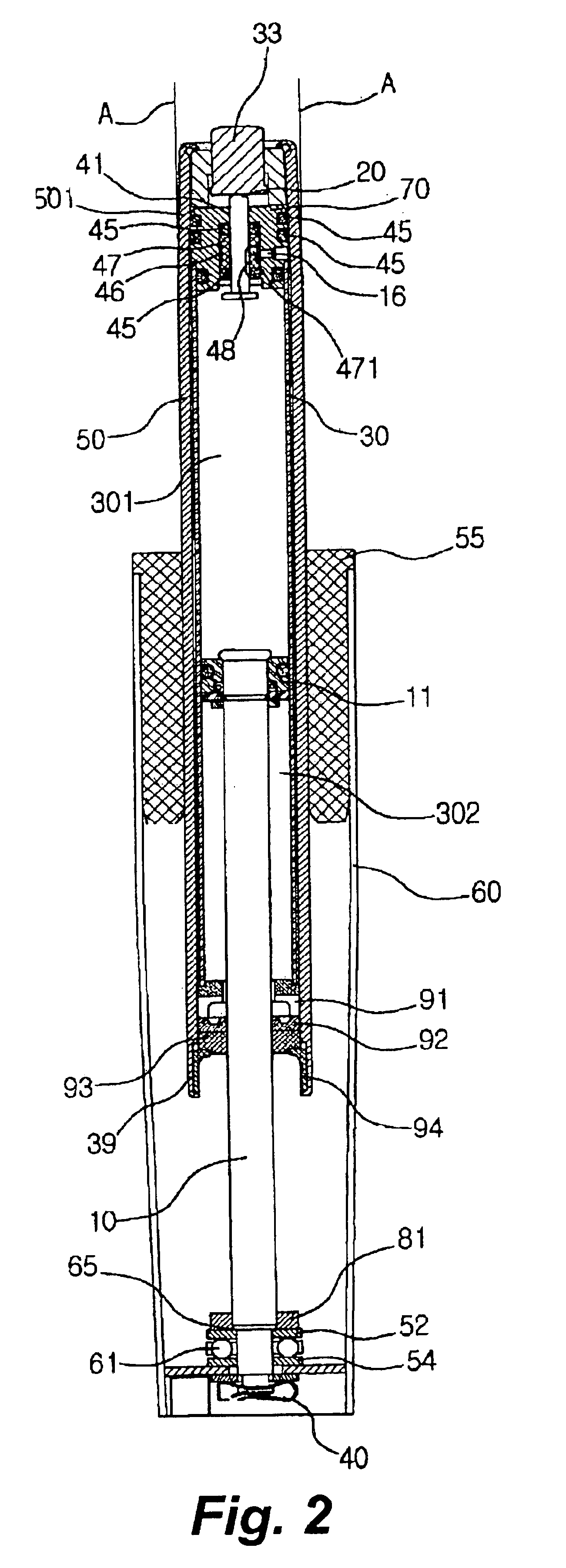
FIG. 1 is a cross-sectional view of a gas cylinder according to the present invention

Referring to FIG. 1, the cylinder type gas cylinder includes: a base tube 60 of a cylindrical shape; a tube guide 55 installed in the inside of the base tube 60; a spindle 50 formed in the inside of the tube guide 55; a piston rod 10 whose one end is fixed on a lower end of the base tube 60, for moving the spindl...


PUM


Abstract

Disclosed is a gas cylinder including: a spindle at least having a flange washer of a cavity shape having a region D1 and a region D2 whose inner diameters are different; a piston inserted to the open inside of the spindle; a piston rod whose one end is fixed in the piston; a base tube having a mounting member on which the lower end of the spindle is mounted with the mounting member inserted to the flange washer; and a pipe holder inserted to the tapered portion in the upper part of the spindle.

Description

BACKGROUND OF THE INVENTION1. Field of the InventionThe present invention relates to a gas cylinder for use in a table and a chair, for adjusting a height of a table and a chair, etc., and more particularly to a gas cylinder capable of increasing the size of a primary axis (spindle) for use in the gas cylinder, specifically increasing up and down movement width (stroke) of a spindle even at a status that the whole size of the gas cylinder is the same.2. Background of the Related ArtA gas cylinder is an apparatus for use in an impulse buffering apparatus of an automobile, a table or a chair, for making a product installed on the gas cylinder more convenient by reducing impulse applied from the outside, or by applying restoring force in one direction. The gas cylinder according to the present invention does not exclude application to different usage such as an impulse buffering apparatus, but the gas cylinder more preferably applicable to a chair, will be described as an example.The g...

Claims


Application Information

Patent Timeline
Patent Type & Authority Patents(United States)
IPC IPC(8): A47C1/02F16M11/00A47C3/30
CPCA47C3/30
Inventor JEON, YOUNG SANG
Owner SAMHONGSA
Why Eureka
Try Eureka