Polarized beam splitter and projection-type image display using it

Inactive Publication Date: 2005-01-11
FUJI PHOTO OPTICAL CO LTD
View PDF6 Cites 7 Cited by
  • Summary
  • Abstract
  • Description
  • Claims
  • Application Information

AI Technical Summary

Benefits of technology

The present invention relates to polarized beam splitters in which astigmatism caused by an inclined intermediate layer therein can be favorably corrected. Also, the present invention relates t

Problems solved by technology

However, that astigmatism is not a negligible factor in reducing resoluti

Method used


Image

  • Polarized beam splitter and projection-type image display using it
  • Polarized beam splitter and projection-type image display using it
  • Polarized beam splitter and projection-type image display using it

Examples


embodiment 1

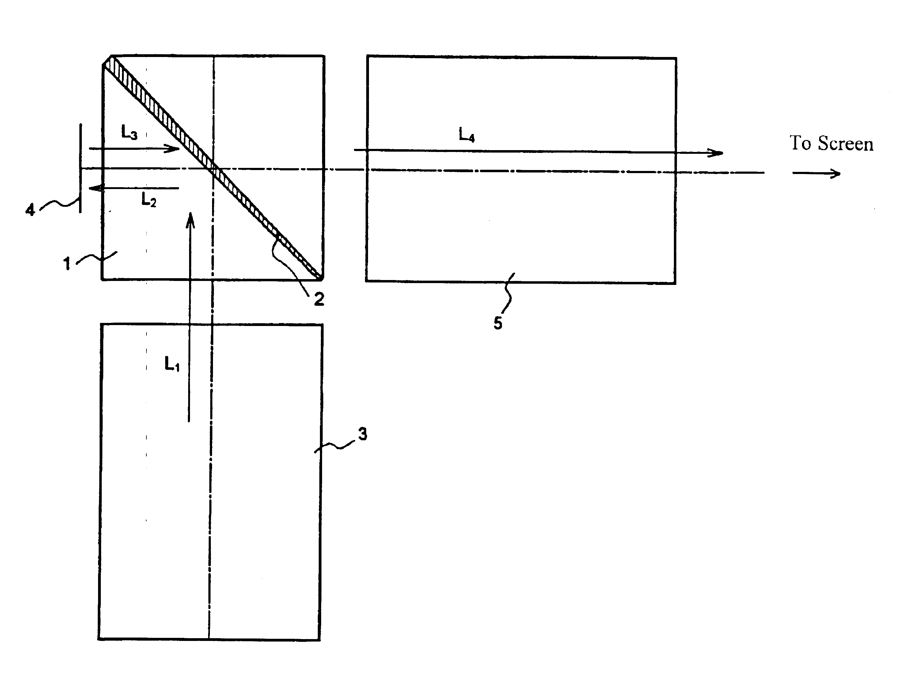
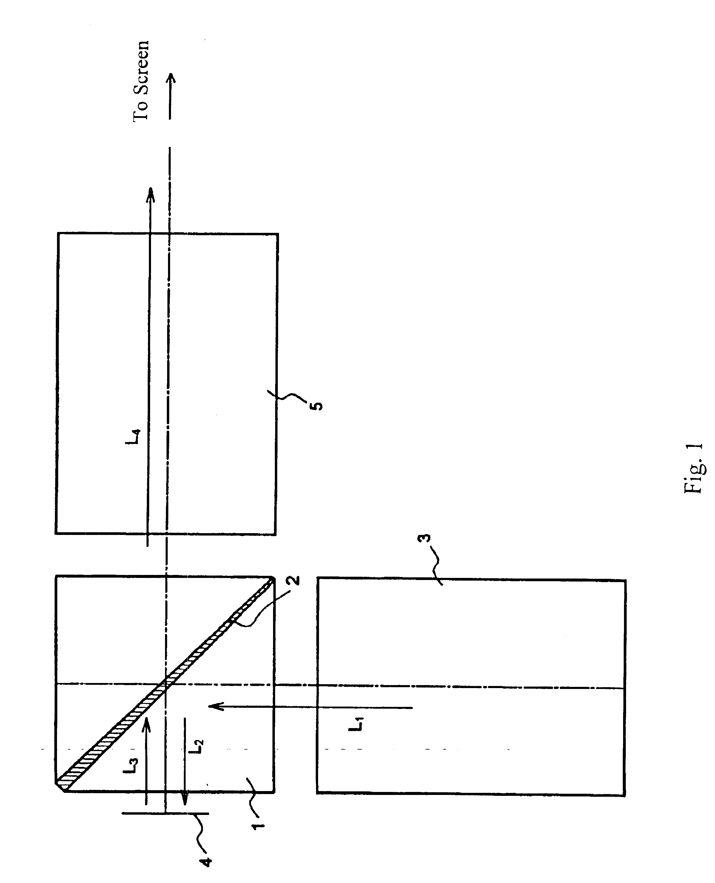
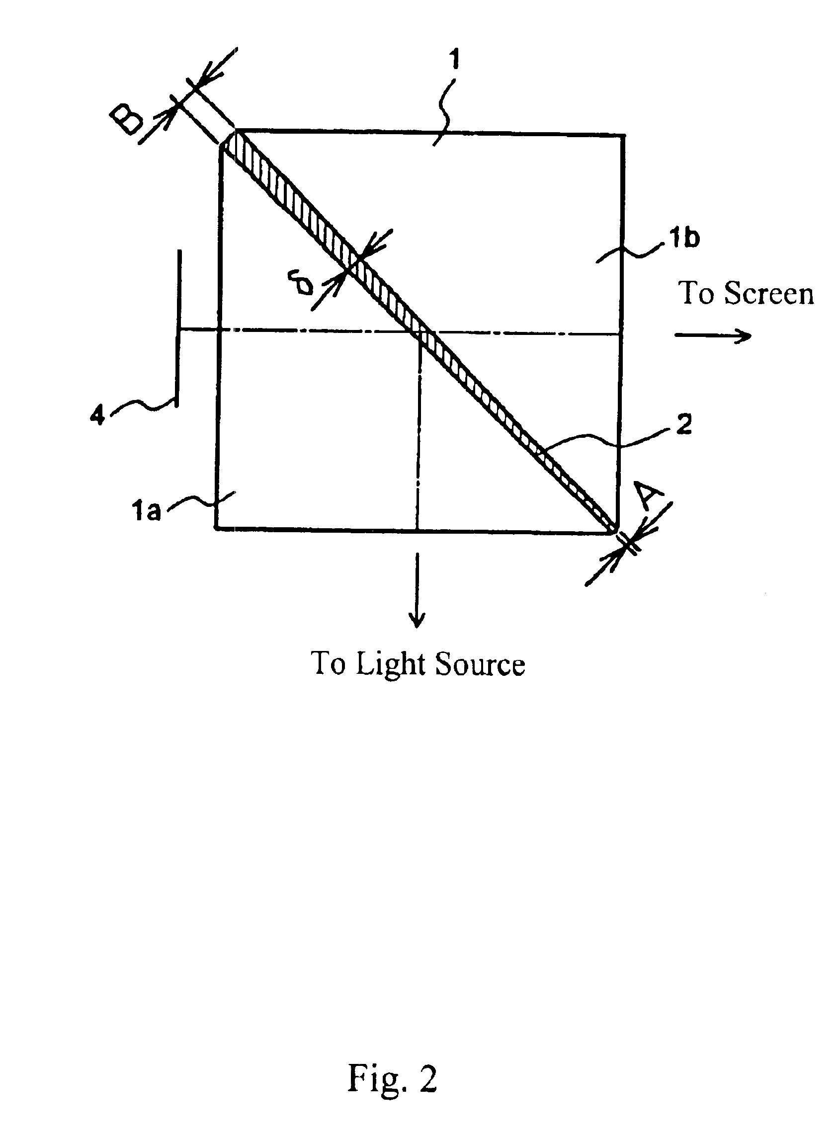
FIG. 1 shows a schematic cross-sectional view of a projection image display device of Embodiment 1. FIG. 2 shows an enlarged view of the PBS 1 shown in FIG. 1. The projection image display device includes a light source (not shown), an illumination optical system 3 including a time-sharing color separating system, a PBS 1 including a wedge-shaped intermediate layer 2 according to the present invention, an LCOS 4 as an image display element, and a projection lens 5. The lower surface of the intermediate layer 2 is inclined forty-five degrees relative to the incident light, and its wedge shape is such that the thick part of the intermediate layer 2 is located near the incident surface of light from the LCOS 4 and the thin part is located away from it. The PBS 1 satisfies Condition (1) above in which Np is the refractive index of the material of the two prisms forming the PBS 1 and Nc is the refractive index of the adhesive forming the adhesive layer of the intermediate layer 2.

Light L...

embodiment 2

FIG. 4 shows a schematic cross-sectional view of a projection image display device of Embodiment 2. The projection image display device includes a light source and an illumination optical system (not shown), a Philips prism 16, which is not polarization sensitive, as a color separating and combining device, a PBS 11 including a wedge-shaped intermediate layer 12 according to the present invention, LCOSs 14a, 14b, and 14c as image display elements, and a projection lens 15.

PBS 11 is nearly the same as PBS 1 of Embodiment 1 and, therefore, a detailed explanation of its structure is omitted here. The intermediate layer 12 is inclined by approximately forty-five degrees relative to the incident light. The thick part of the wedge shape is located near the incident surface of light from the LCOSs 14a, 14b, and 14c and the thin part is located away from the incident surface. The PBS 11 satisfies Condition (1) in which Np is the refractive index of the material of the two prisms forming the...

embodiment 3

FIG. 5 shows a schematic cross-sectional view of a projection image display device of Embodiment 3. The projection image display device includes a light source and an illumination optical system (not shown), a Philips prism 26, which is not polarization sensitive, as a color separating and combining device, PBSs 21a, 21b, and 21c including wedge-shaped intermediate layers 22a, 22b, and 22c, respectively, according to the present invention, LCOSs 24a, 24b, and 24c as image display elements, and a projection lens 25.

The PBSs 21a, 21b, and 21c are nearly the same as the PBS 1 of Embodiment 1, and therefore, detailed explanations of their construction is omitted here. The intermediate layers 22a, 22b, and 22c are inclined by approximately forty-five degrees relative to the incident light. The thick parts of the wedge shapes are located near the incident surfaces of light from the LCOSs 24a, 24b, and 24c and the thin parts are located away from the incident surfaces. The PBSs 21a, 21b, a...


PUM


Abstract

A polarized beam splitter includes an inclined intermediate layer between two glass prisms. The intermediate layer includes an adhesive layer and a polarized light separating membrane. The intermediate layer may be wedge-shaped in order to compensate for or to cancel astigmatism of light transmitted by the polarized beam splitter caused by the inclination of the intermediate layer. The polarized beam splitter may also be formed with the refractive indexes of the glass and the adhesive of the adhesive layer chosen to reduce astigmatism. Embodiments of three-color projection image display devices that use the polarized beam splitter are also disclosed. The three-color projection image display devices may use one or three polarized beam splitters with a Philips prism or use two polarized beam splitters with a COLORQUAD.

Description

BACKGROUND OF THE INVENTIONRecently, reflective image display elements collectively called LCOS (Liquid Crystal on Silicon) have become of great interest as image display elements for projection image display devices. Two of the characteristics of an LCOS that are advantageous for such devices are high aperture efficiency compared to transmissive image display elements, which helps achieve bright images, and high resolution for the size of the LCOS. The LCOS controls the polarization direction of the light that it reflects in order to turn itself ON and OFF in use with a polarization sensitive beam splitter (hereinafter termed a polarized beam splitter or PBS). The PBS is generally provided in the optical path between an image display element and a projection lens.A PBS used in a projection image display device is generally formed of two isosceles right triangular prisms with their hypotenuse surfaces bonded together (see, for example, Japanese Laid-Open Patent Application 2002-0403...

Claims


Application Information

Patent Timeline
IPC IPC(8): G02B5/04G02B5/30G02B27/28G03B21/00
CPCG02B5/04
Inventor YONEYAMA, KAZUYANAKAZAWA, KIMIAKI
Owner FUJI PHOTO OPTICAL CO LTD
Why Eureka
Try Eureka