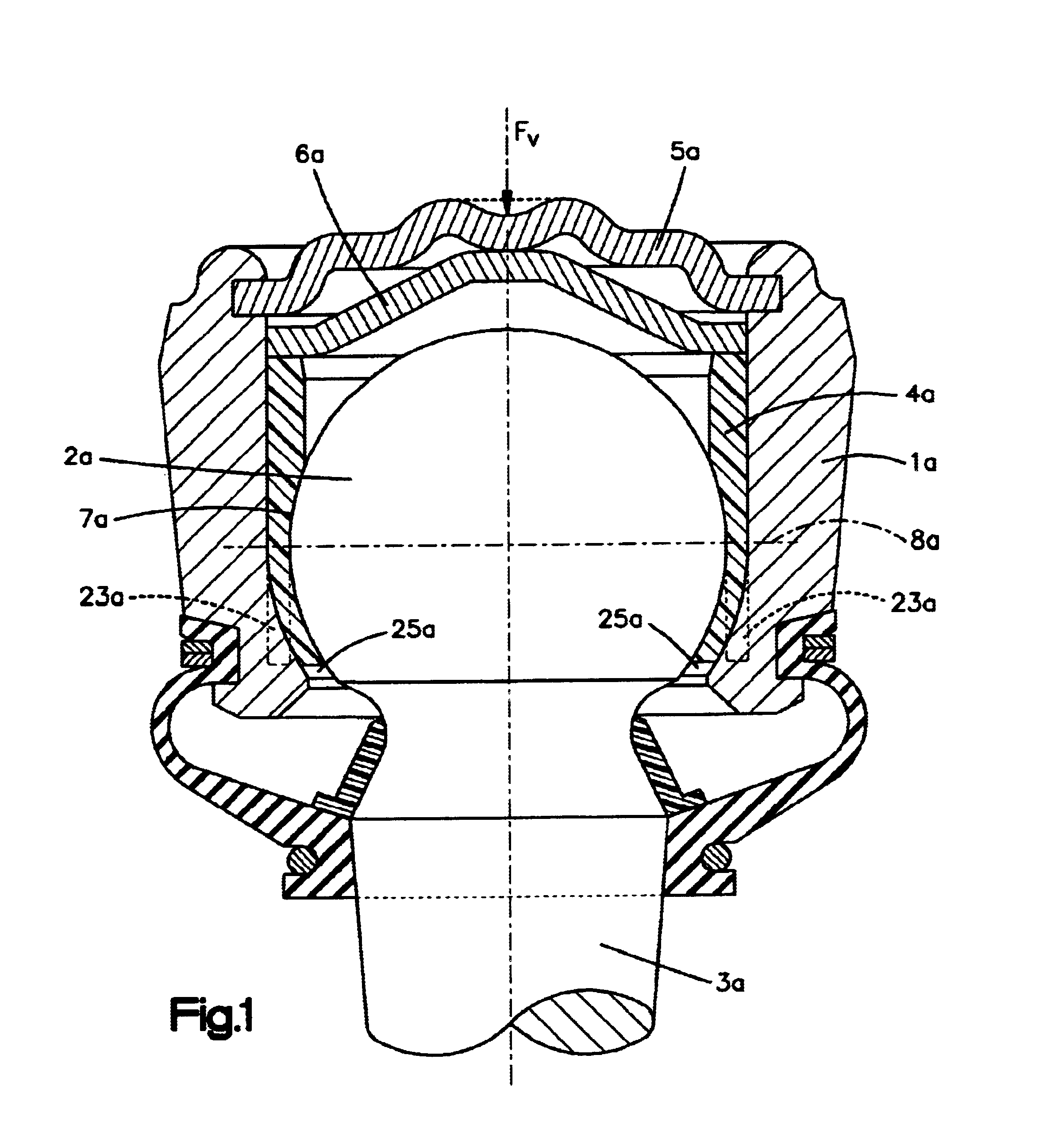
To produce the compressive force permanently acting on the bearing shell, the present invention proposes plastically to deform the housing cover in axial direction of the ball pivot with a specifically definable force. A disk made of an elastic material and disposed between housing cover and bearing shell is elastically deformed by the plastic deformation of the housing cover. This generates a preloading force that is applied to the bearing shell as a permanently acting compressive force. Thus, a defined pressing in of the housing cover makes it possible to achieve an exactly definable preloading force of the ball-and-socket joint. According to a particular
advantage of the invention, both the housing cover and the disk have an outwardly facing trapezoidal curvature. The inside of the housing cover rests against and fully contacts the disk in the area of the trapezoidal curvature based on a defined applied force and a deformation of the housing cover. This effect can furthermore be enhanced in that the torque of the ball pivot is measured or monitored as the housing cover is pressed in, and the measured data is used to control the pressing-in force.
, both the housing cover and the disk have an outwardly facing trapezoidal curvature. The inside of the housing cover rests against and fully contacts the disk in the area of the trapezoidal curvature based on a defined applied force and a deformation of the housing cover. This effect can furthermore be enhanced in that the torque of the ball pivot is measured or monitored as the housing cover is pressed in, and the measured data is used to control the pressing-in force.
According to an alternative embodiment, the compressive force permanently acting on the bearing shell is produced by means of a spring that is arranged between the housing cover and the bearing shell and supported against the joint housing via the housing cover. With particular
advantage, it is proposed that the spring is a trapezoidal disk spring with an outward curvature. When the joint housing is closed with a rigid housing cover, the disk spring disposed between bearing shell and housing cover is compressed and the
resultant spring force permanently acts on the bearing shell in axial direction of the pivot pin in the form of a compressive force. By selecting a corresponding disk spring and its initial stress, the disk
spring force and thus also the preloading force of the ball-and-socket joint can be adjusted. According to a further advantageous proposal of the invention, an additional load transmission disk may be disposed between disk spring and bearing shell to optimize introduction of the force into the bearing shell. In a further advantageous embodiment, the contact area between spring and disk is designed as a deformable area. During
assembly, after flattening of the spring, this area is deformed to a sufficient degree until the bearing shell has reached its axial end position. The initial preloading of the joint is thus independent of the tolerances of the individual components and the size of the
spring force.
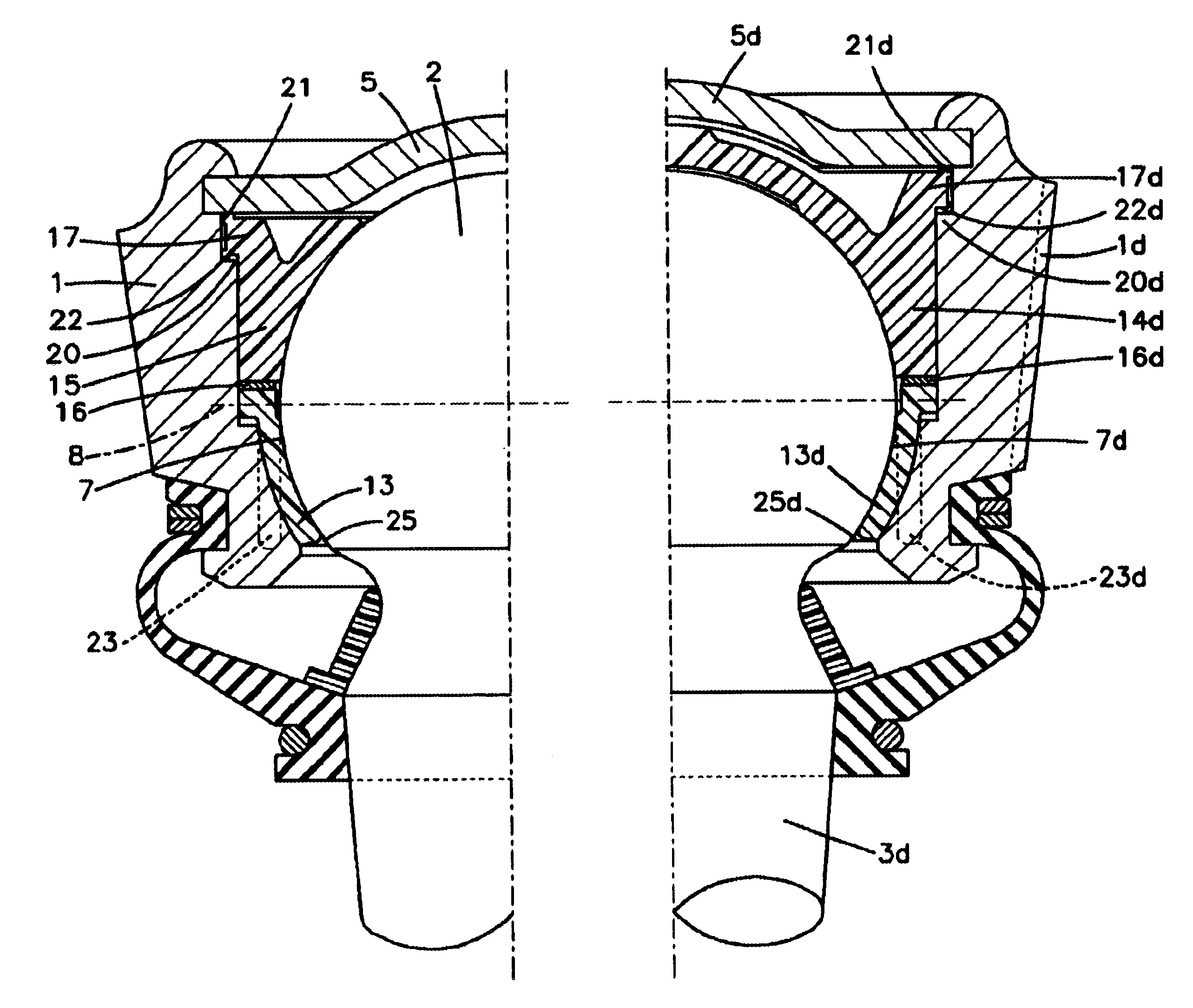
According to an alternative embodiment, the bearing shell arranged between ball head and joint housing has a two-part design and is divided into an upper shell and a lower shell. This partitioning of the bearing shell into two parts advantageously creates two mutually independent functional areas that may be designed according to the requirements they are intended to meet. For example, the upper shell serves to compensate the inaccuracies due to the manufacturing tolerances of the joint members, whereas the lower shell compensates wear.
To compensate the inaccuracies due to the manufacturing tolerances in the
assembly of the
ball joint, the invention proposes that the upper shell, on the housing cover side, be provided with a collar, which in the assembled state of the ball-and-socket joint is wedged between the housing cover and a housing shoulder. To assemble the ball-and-socket joint, a compressive force acting in axial direction of the ball pivot is generated on the cover side and applied via the housing cover to press the bearing shells into the gap between ball head and housing. The compressive force acting during assembly is transmitted from the upper shell to the lower shell. The inaccuracies due to the manufacturing tolerances of the joint members can be compensated due to a plastic deformation of the collar arranged between the actual upper shell and the housing cover. The axial end position of the upper and lower shell is established as a function of the tolerances of the individual components, such that, irrespective of manufacturing tolerances, the ball head is supported in the bearing shell and different freedoms of movement of the ball-and-socket joints are avoided.
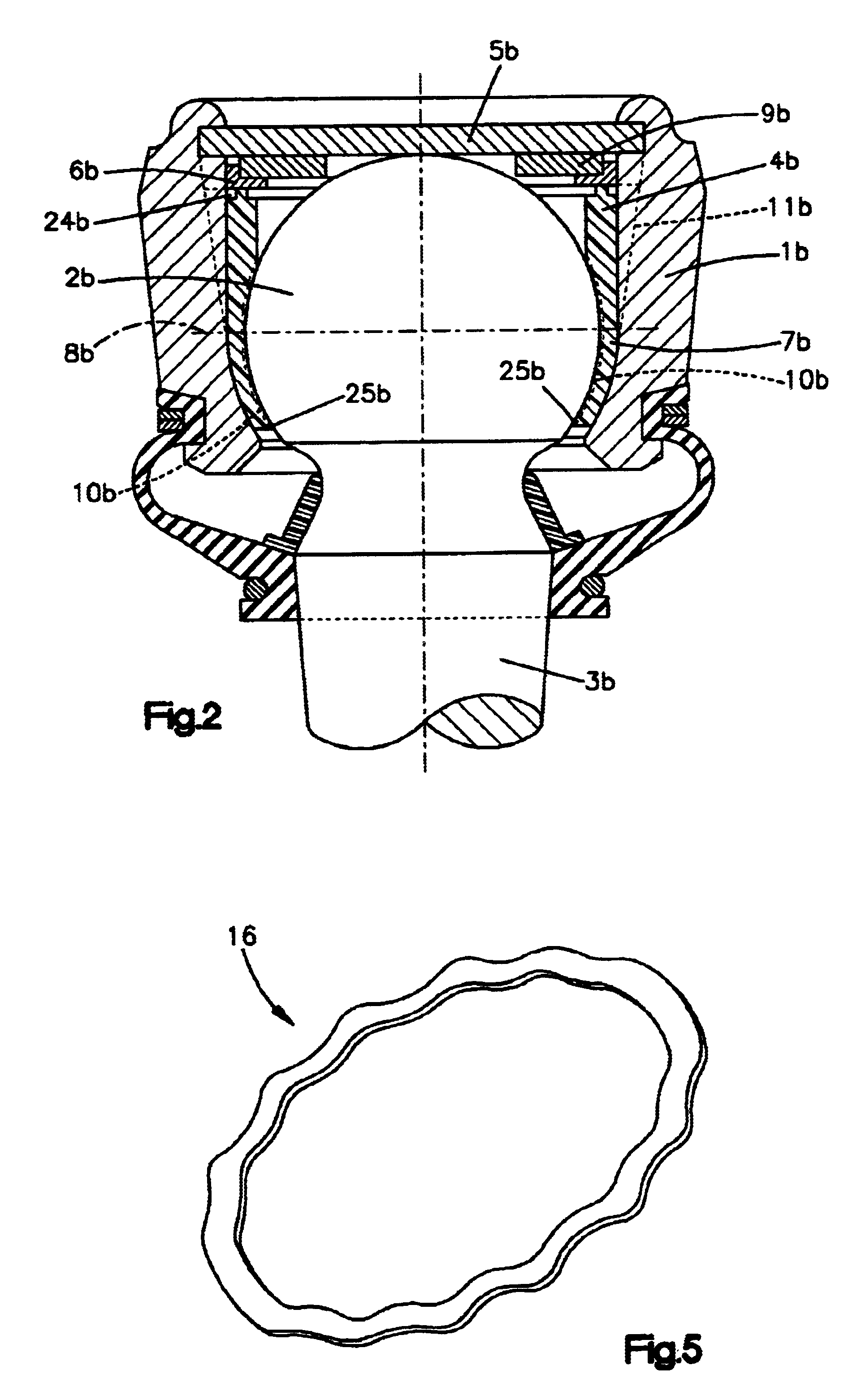
According to a further feature of the invention, to compensate wear of the bearing shell, a spring element is disposed in axial direction between upper shell and lower shell. In the assembled state, this spring element is supported against the housing cover via the upper shell and produces a compressive force permanently acting on the lower shell, which causes a continuous advancement of the lower shell as wear occurs. This allows a “self-adjustment” of the lower shell of the ball head under the action of axial-elastic wedge effects that remain always the same and achieves, on the one hand, motive torques that are largely constant and on the other hand essentially unchanged elastic properties of the bearing shell. This advantageously prolongs the life of the ball-and-socket joint. According to a further feature of the invention, the spring element disposed between upper shell and lower shell is a spring
washer of a wave-shaped design that is pushed up completely after assembly and thus can transmit the full magnitude of the assembly compressive force to the lower shell.

