Connector for preventing half fitting condition

a technology of connectors and connectors, applied in the direction of incorrect coupling prevention, coupling device connection, electrical equipment, etc., can solve problems such as errors

Inactive Publication Date: 2005-01-11
YAZAKI CORP
View PDF5 Cites 9 Cited by
  • Summary
  • Abstract
  • Description
  • Claims
  • Application Information

AI Technical Summary

Benefits of technology

It is therefore an object of the present invention to provide a half-fitting prevention connector in which when male and female connectors are disposed in a half-fitted condition, this half-fitted condition can be positively detected.
In the above configuration, in the half-fitted condition before the completely-fitted condition of the first and second connectors, the frictional force between the elastic lock arm and the projection is reduced, and therefore the elastic lock arm can smoothly slide over the projection, and can be elastically deformed upwardly.
Therefore, an elastic restoring force of the elastic lock arm is increased, and a resilient force, tending to urge the female connector back into the half fitting position in the disengaging direction, is produced, so that the half-fitted condition can be positively detected. Therefore, an incompletely-connected condition of the tab terminal and tab receiving terminal in the half-fitted condition can be positively prevented.

Problems solved by technology

Therefore, there has been encountered a problem that the advance of the female connector 80 stops, so that the tab terminals 72 are electrically connected respectively to the tab-receiving terminals 81 in an unstable electrical connecting condition.
Particularly when the tab terminals 72 and the tab receiving terminals 81 are used as signal lines so as to feed a very small current, there has been encountered a problem that an error develops.

Method used


Image

  • Connector for preventing half fitting condition
  • Connector for preventing half fitting condition
  • Connector for preventing half fitting condition

Examples


Embodiment Construction

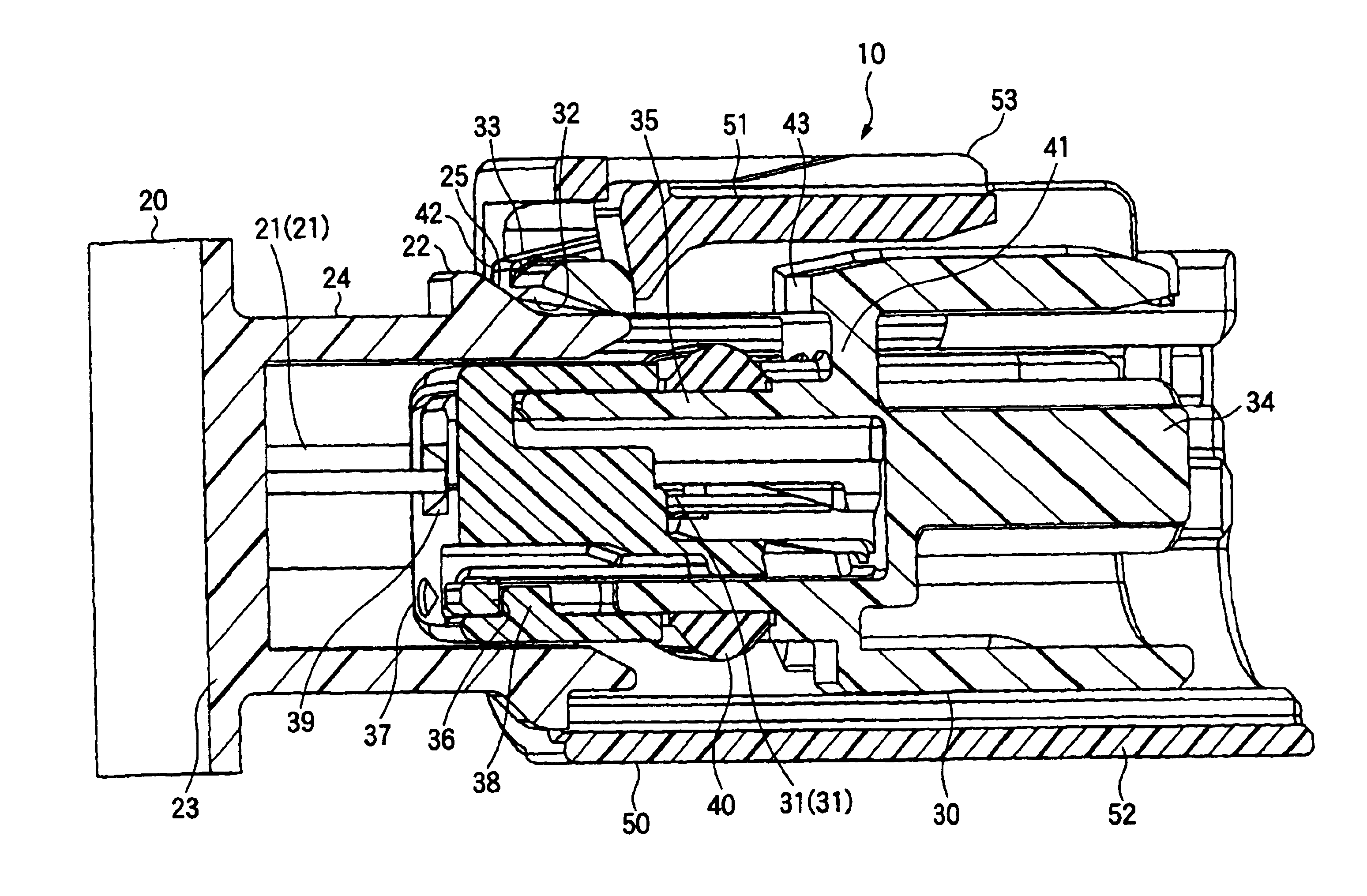
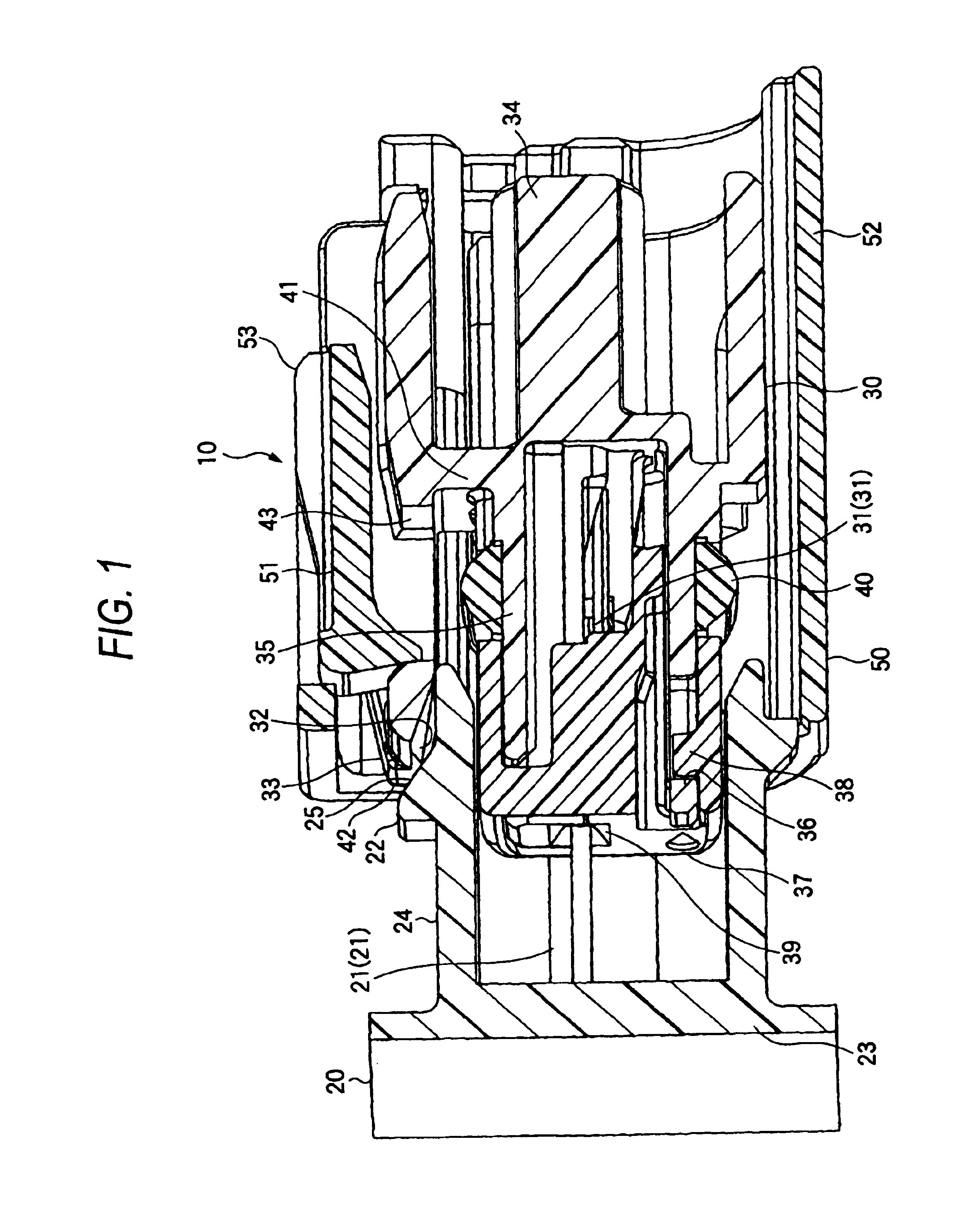
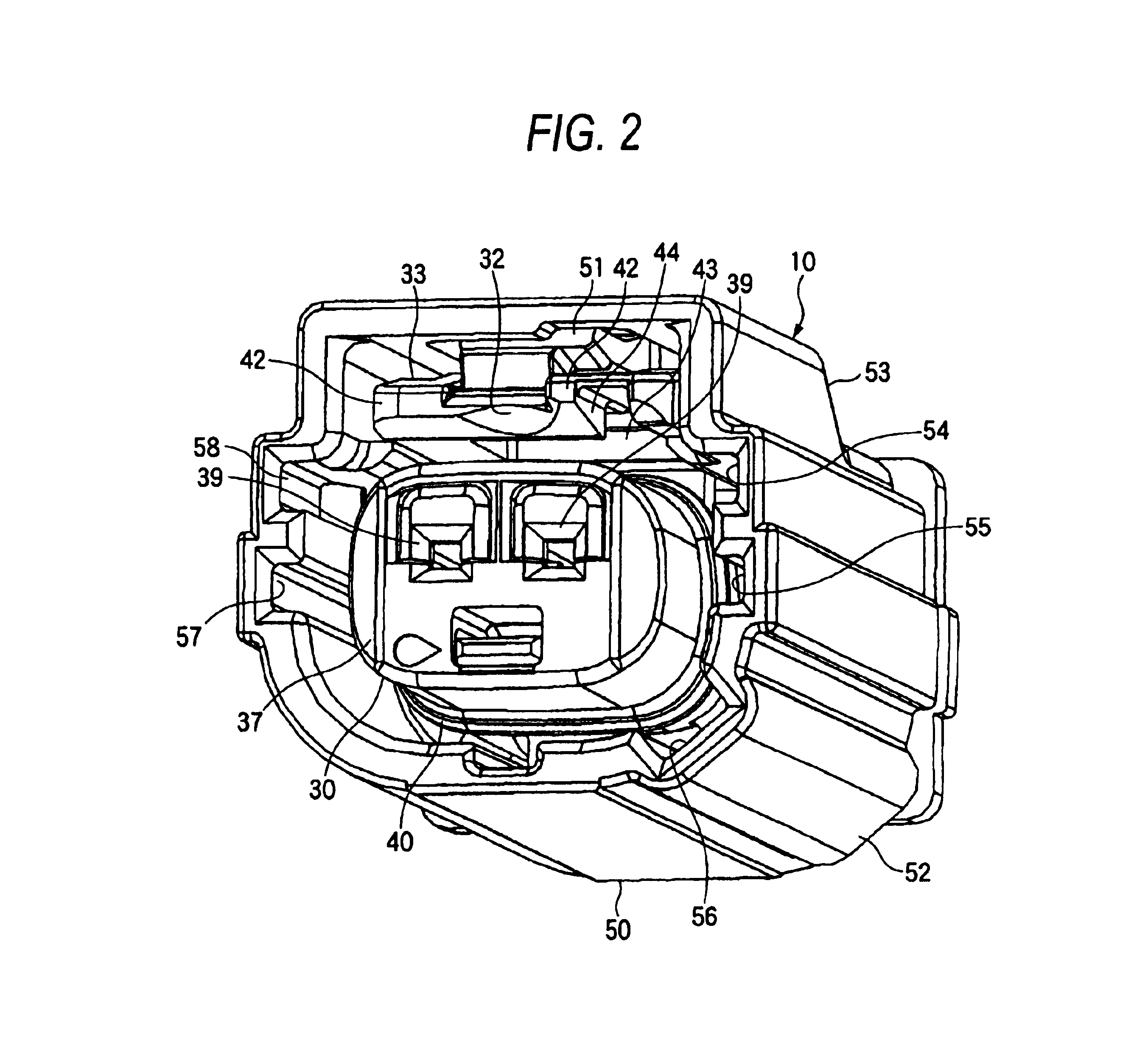
One preferred embodiment of a half-fitting prevention connector of the present invention will now be described in detail with reference to FIGS. 1 to 3. FIG. 1 is a cross-sectional view of one preferred embodiment of the half-fitting prevention connector of the invention, showing an initially-fitted condition of male and female connectors begin, FIG. 2 is a perspective view showing a condition in which a fitting detection member is mounted on the female connector FIG. 1, and FIG. 3 is a cross-sectional view showing a half-fitted condition of the male and female connectors of FIG. 1 before a completely-fitted condition.

As shown in FIG. 1, the half-fitting prevention connector 10 of this embodiment includes the male connector 20 which has a tab terminals 21 and a projection 22, the female connector 30 which has a tab-receiving terminals 31 and an elastic lock arm 33 having a recessed portion 32, and the fitting detection member 50 which has an elastic retaining arm 51.

The male connect...


PUM


Abstract

A connector includes a first connector, a second connector and a fitting detection member. The first connector includes a tab terminal and a projection. The second connector includes a tab receiving terminal for electrical connection to the tab terminal and an elastic lock arm for sliding over the projection when the second connector is fitted into the first connector. The fitting detection member is mounted on the second connector so as to slide in a direction of fitting of the first and second connectors. The fitting detection member is engaged with the elastic lock arm in a half fitting condition of the first and second connectors. The fitting detection member is slidable to a completely-fitted detecting position in a completely-fitted condition of the male and second connectors. The reduction member which reduce a frictional force generated by a contact between the projection and the elastic lock arm is formed on at least one of the projection and the elastic lock arm.

Description

BACKGROUND OF THE INVENTIONThis invention relates to a half-fitting prevention connector in which when a pair of male and female connectors are fitted together, a half-fitted condition of the male and female connectors is detected by determining that whether or not a fitting detection member, mounted on one of the two connectors, can be slid into a proper fitting detection position.FIGS. 4 and 5 show a related half-fitting prevention connector. The half-fitting prevention connector 60, shown in FIGS. 4 and 5, includes a male connector 70, a female connector 80, and a fitting detection member 90.The female connector 70 includes a tubular portion 71 within which tab terminals 72 are provided, and a projection 73 is formed on the tubular portion 71. The male connector 70 is connected to a connector of a control circuit or the like, and the tab terminals 72 are electrically connected to this control circuit.The female connector 80 has tab-receiving terminals 81 received therein, and tab...

Claims


Application Information

Patent Timeline
Patent Type & Authority Patents(United States)
IPC IPC(8): H01R13/641H01R13/64H01R13/627
CPCH01R13/641H01R13/627
Inventor ENDO, TOMOMITAGUCHI, NAOTO
Owner YAZAKI CORP
Why Eureka
Try Eureka