Hybrid spool valve for multi-port pulse tube

a multi-port, hybrid technology, applied in the direction of servomotors, pressure relieving devices on sealing faces, lighting and heating apparatuses, etc., can solve the problems of spool, seat, sleeve, etc., and achieve the effect of reducing the torque required to turn the valve and simple construction

Active Publication Date: 2009-06-18
SUMITOMO HEAVY IND LTD +1
View PDF22 Cites 11 Cited by
  • Summary
  • Abstract
  • Description
  • Claims
  • Application Information

AI Technical Summary

Benefits of technology

[0008]The present invention provides a solution to these problems in a simple construction by using a rotary spool valve having radial clearance to control flow to and from the regenerator, and using face seal ports on the end of the spool to control flow to and from the pulse tubes. The diameter of

Problems solved by technology

The spool, sleeve, and sea

Method used


Image

  • Hybrid spool valve for multi-port pulse tube
  • Hybrid spool valve for multi-port pulse tube
  • Hybrid spool valve for multi-port pulse tube

Examples


Embodiment Construction

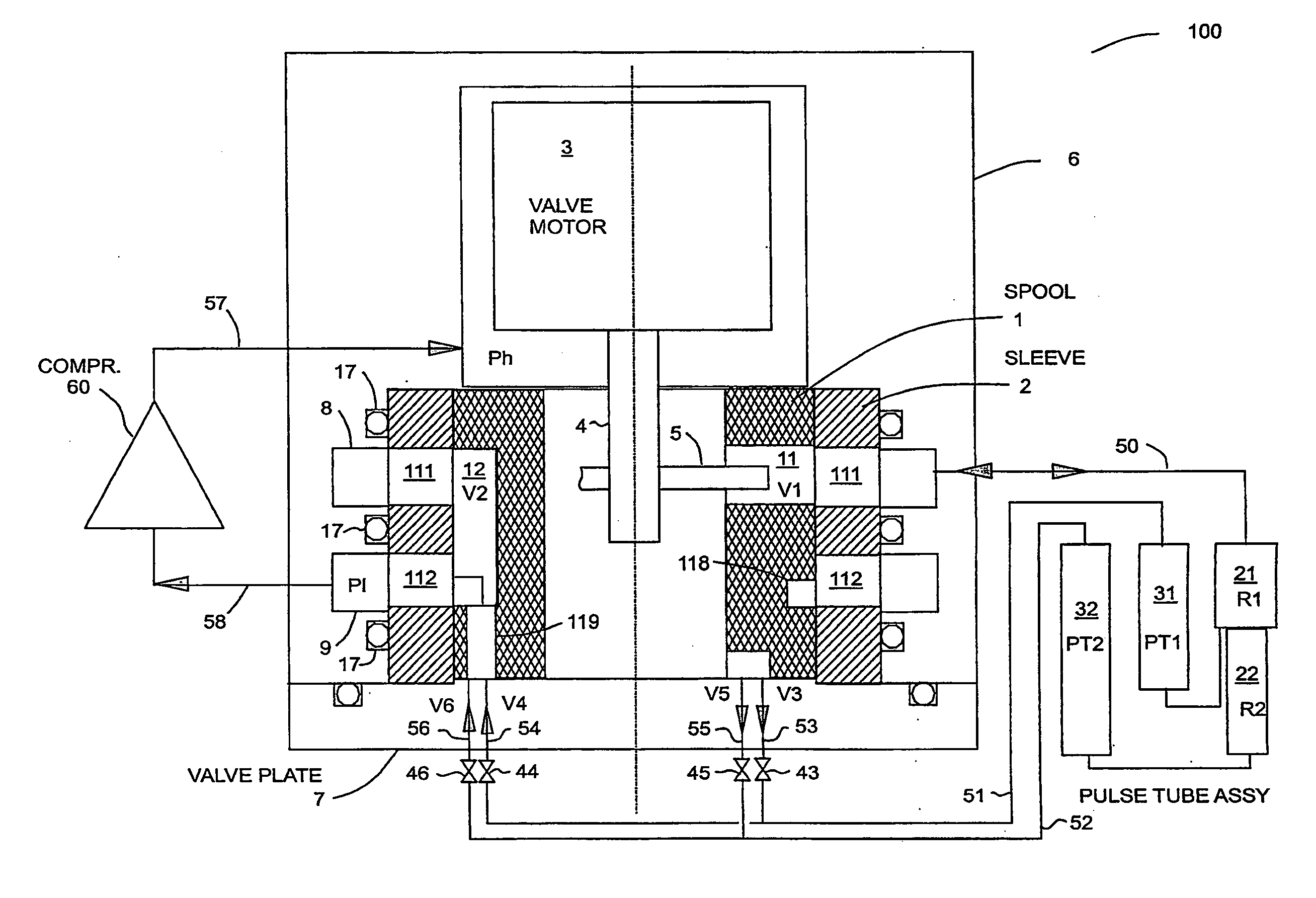
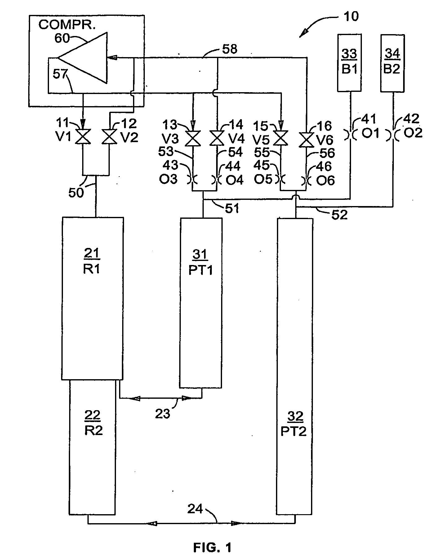
[0016]FIG. 1 is a schematic of a two-stage four-valve pulse tube refrigerator 10 that shows the gas flow paths through the system. FIG. 1 illustrates refinements in a basic two-stage four-valve pulse tube refrigerator such as that illustrated in FIG. 9 of U.S. Pat. No. 6,256,998. High-pressure gas, Ph, flows from compressor 60 through gas line 57 to valves 11 (V1), 13 (V3), and 15 (V5). Low-pressure gas, Pl, returns to compressor 60 from valves 12 (V2), 14 (V4), and 16 (V6) through line 58. Valves V1 and V2 control the flow to and from regenerator 21 (R1) through line 50.

[0017]Valve V3 controls the flow to the first stage pulse tube 31 (PT1) through line 53, orifice 43 (O3) and line 51. Valve V5 controls the flow to the second stage pulse tube 32 (PT2) through line 55, orifice 45 (O5) and line 52. Valve V4 controls the flow from PT1 through line 51, orifice 44 (O4) and line 54. Valve V6 controls the flow from PT2 through line 52, orifice 46 (O6) and line 56.

[0018]Some of the gas tha...


PUM


Abstract

The problems of reducing the torque required to turn the valve, eliminating wear dust, and extending the life of the valves in Gifford McMahon (G-M) type multi-port pulse tube refrigerators are solved by using a rotary spool valve having radial clearance to control flow to and from the regenerator, and using face seal ports on the end of the spool to control flow to and from the pulse tubes.

Description

BACKGROUND OF THE INVENTION[0001]The present invention relates to Gifford McMahon (G-M) type multi-port pulse tube refrigerators. G-M type pulse tubes consist of a compressor, a valve mechanism, and an expander. The present invention improves on a previous rotary valve disc and valve seat mechanisms. The improvement lies in replacing the face seal ports for flow to and from the regenerator with a rotary spool valve having radial clearance, while retaining the face seal ports for flow to and from the pulse tubes.[0002]It has been found that best performance at 4 K has been obtained with a pulse tube as shown in FIG. 9 of Gao, U.S. Pat. No. 6,256,998. This design has two valves controlling flow to the regenerator, and four valves controlling flow to the warm ends of the pulse tubes, which open and close in the sequence shown in FIG. 11 of U.S. Pat. No. 6,256,998. The single stage version of this pulse tube has four valves, two to the regenerator and two to the pulse tube, thus this co...

Claims


Application Information

Patent Timeline
IPC IPC(8): F15B9/00F15B9/08F16K11/06
CPCF16K31/041F25B9/10F25B9/145F25B2309/002F25B2309/1427F25B2309/1408F25B2309/1411F25B2309/14181F25B2309/14241F25B2309/006Y10T137/87032
Inventor LONGSWORTH, RALPH C.
Owner SUMITOMO HEAVY IND LTD
Why Eureka
Try Eureka