Liquid ejection apparatus having wiper for wiping ejection surface

a technology of liquid ejection apparatus and wiper, which is applied in the direction of printing, etc., can solve the problems of large unavoidable movement of the wiper member when the driven member is driven, and easy so as to facilitate deterioration of the wiper, the frictional force between the wiper and the cleaning member is large, and the wiper is easily deteriorated.

Active Publication Date: 2017-09-12
BROTHER KOGYO KK
View PDF18 Cites 10 Cited by
  • Summary
  • Abstract
  • Description
  • Claims
  • Application Information

AI Technical Summary

Benefits of technology

[0006]In the apparatus above, however, when it is necessary to rotate the cam gear in only one rotational direction, the cam gear must be rotated once in the one rotational direction to return the cam gear to the separation position, after the cam gear starts to rotate and the wiper member starts to move away from the separation position. To be more specific, when the apparatus above includes another driven member (e.g., a valve mechanism and a capping mechanism) which is not the wiper member and is driven by the rotation of the cam gear in the one rotational direction, the wiper member is unavoidably moved when the driven member is driven. On this account, each time the cam gear is rotated to drive the driven member, the wiper contacts with the cleaning member. The wiper is therefore easily deteriorated. In particular, when the cam gear is rotated while the wiper has not wiped the ejection surface, the frictional force between the wiper and the cleaning member is large because an amount of liquid adhered to the wiper is small, with the result that the deterioration of the wiper is facilitated.
[0007]In the meanwhile, a known wiper holder includes a contact part which is provided to oppose an opposing surface of the wiper. The opposing surface is a downstream surface in a wiping direction of a supporting part of the wiper, the supporting part being close to the wiper holder. In this arrangement, after the cleaning of the wiper, when the wiper is moved in the direction opposite to the direction in the cleaning to return to the original position, the wiper is in contact with the cleaning member. In this state, the leading end of the wiper is warped and the opposing surface is supported by the contact plate. This is disadvantageous in that the wiper becomes less easily warped and the wiper is less easily returned to the original position.
[0009]The first object of the present invention is to provide a liquid ejection apparatus which is able to restrain the deterioration of a wiper.
[0010]The second object of the present invention is to provide a liquid ejection apparatus in which the return of a wiper after removal of liquid adhered to the wiper is facilitated.
[0011]The third object of the present invention is to provide a liquid ejection apparatus in which a wiper is cleaned while increase in the size of a cam in a radial direction is restrained.

Problems solved by technology

To be more specific, when the apparatus above includes another driven member (e.g., a valve mechanism and a capping mechanism) which is not the wiper member and is driven by the rotation of the cam gear in the one rotational direction, the wiper member is unavoidably moved when the driven member is driven.
The wiper is therefore easily deteriorated.
In particular, when the cam gear is rotated while the wiper has not wiped the ejection surface, the frictional force between the wiper and the cleaning member is large because an amount of liquid adhered to the wiper is small, with the result that the deterioration of the wiper is facilitated.
This is disadvantageous in that the wiper becomes less easily warped and the wiper is less easily returned to the original position.
When the circumferential length of the cam at a lower part of the wiper member is longer than the interval of the neighboring two detection targets, the contact part contacts with a detection target on the cam, with the result that the wiper cannot be cleaned.
This, however, is disadvantageous in that the cam is increased in size.

Method used


Image

  • Liquid ejection apparatus having wiper for wiping ejection surface
  • Liquid ejection apparatus having wiper for wiping ejection surface
  • Liquid ejection apparatus having wiper for wiping ejection surface

Examples


first embodiment

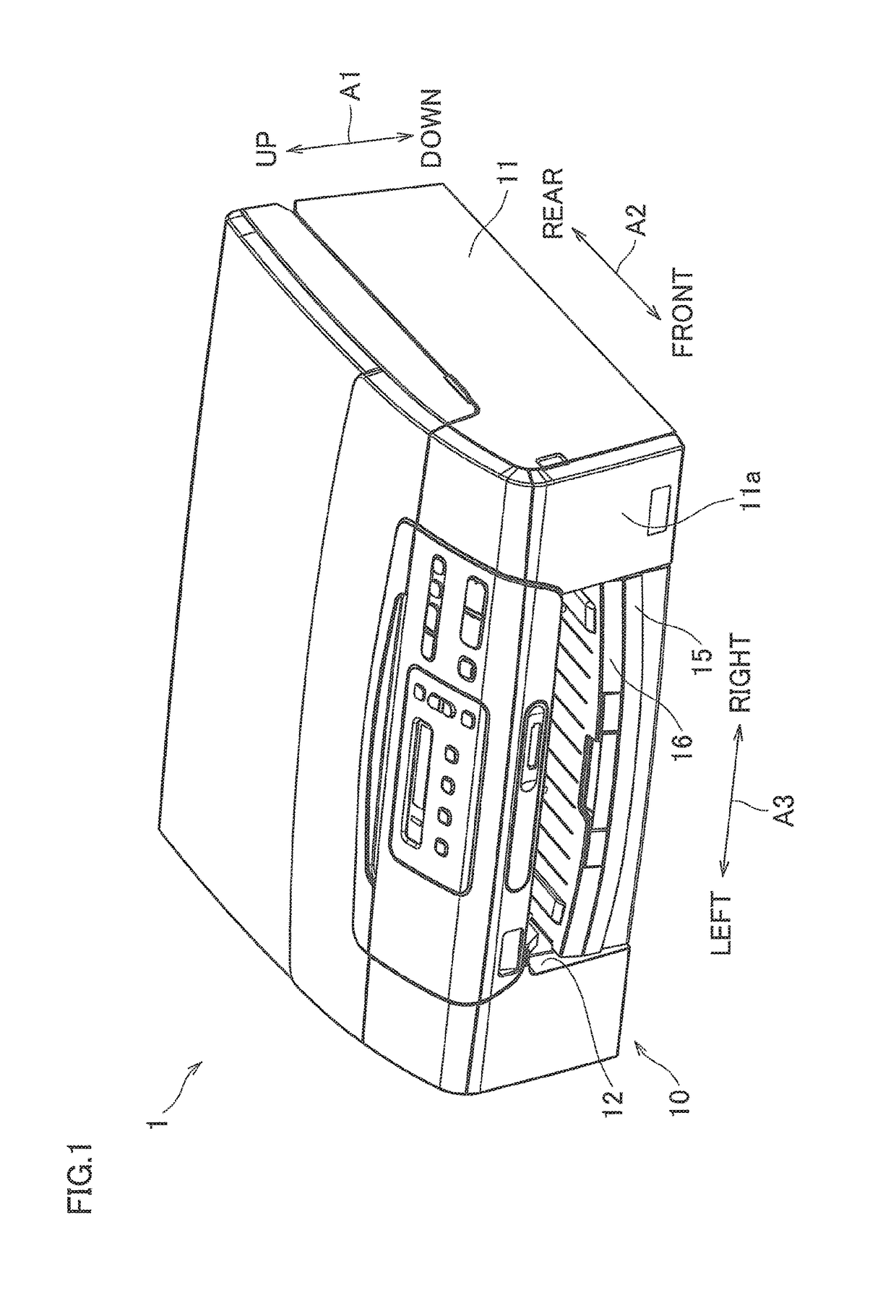
[0057]To begin with, a multifunction machine 1 which employs a printer of the first aspect of the present invention (First Embodiment) will be described. This multifunction machine 1 is installed as shown in FIG. 1 when used. In the present embodiment, three directions indicated by arrows in FIG. 1 are an up-down direction A1, a front-rear direction A2, and a left-right direction A3. The three directions shown in FIG. 1 are used in other figures, too.

[0058]1>

[0059]As shown in FIG. 1, the multifunction machine 1 is basically a thin rectangular parallelepiped member, and a display, an operation button, and the like are provided on an upper surface of the multifunction machine 1. A printer 10 which is an example of a liquid ejection apparatus of the present invention is provided in a lower part of the multifunction machine 1. The multifunction machine 1 has functions such as a scanning function and a printing function.

[0060]The printer 10 includes a housing 11. Substantially at the cen...

second embodiment

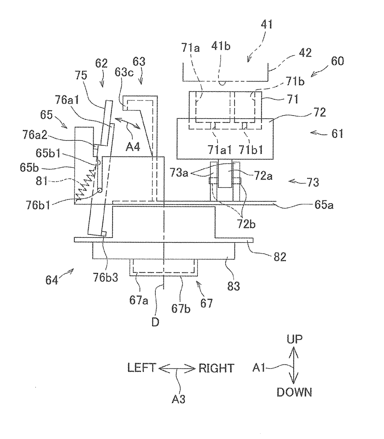
[0173]In Second Embodiment, in the avoiding process, the cleaning member 63 is moved to the non-cleaning position where the wiper 75 and the cleaning member 63 do not contact with each other even if the wiper holder 76 moves from the second position to the first position in the returning process. Alternatively, the cleaning member 63 may be moved to a position where the wiper 75 and the cleaning member 63 contact with each other in the returning process. In this case, in the returning process, the interference with the contact plate 76a1 must be avoided and the contact area between the wiper 75 and the cleaning member 63 is required to small as compared to the contact area in the cleaning process. With this, the contact resistance between the wiper 75 and the cleaning member 63 when the returning process is executed is reduced. This facilitates the return of the wiper holder 76 from the second position to the first position.

[0174]In the avoiding process, the upper edge of the leadin...

third embodiment

[0251]While in Third Embodiment two detection targets 82e and 82f are provided on the rotational cam 82, the number of the detection targets may be three or more. In such cases, among a plurality of intermediate regions formed along the rotational direction A5 (circumferential direction) of the rotational cam 82 and between two detection targets neighboring each other in the rotational direction A5, the region wider than the width of the lower end 76c in the rotational direction A5 is the specific intermediate region. The contact part 82d is provided at a position corresponding to this specific intermediate region, and the lower end 76c passes the specific intermediate region when moving between the first position and the second position. Effects similar to those in the embodiment above are achieved by this arrangement, too. When three or more detection targets are provided on the rotational cam 82, two detection targets constituting the specific intermediate region are first and se...


PUM


Abstract

A wiper moving mechanism moves a wiper member a predetermined distance in an intersecting direction intersecting with an ejection surface, between a wiping position where a wiper of the wiper member is in contact with the ejection surface and a separation position. The cam is rotatable about a rotation shaft and includes a contact part which causes the wiper to make contact with a cleaning member when the contact part makes contacts with a wiper holder. The contact part is configured to be distant from the wiper holder in the intersecting direction when the wiper member is positioned at the wiping position and to be overlapped with a moving range of the wiper holder in the intersecting direction by moving the wiper member by the predetermined distance in the intersecting direction. The contact part has a length which is shorter than the moving range in the intersecting direction.

Description

CROSS REFERENCE TO RELATED APPLICATION[0001]This application claims priority from Japanese Patent Applications No. 2015-070794, No. 2015-070944 and No. 2015-074427 which ware filed on Mar. 31, 2015, the disclosure of which is herein incorporated by reference in its entirety.BACKGROUND OF THE INVENTION[0002]1. Field of the Invention[0003]The present invention relates to a liquid ejection apparatus.[0004]2. Description of Related Art[0005]A known liquid ejection apparatus includes a wiper member which includes a wiper configured to wipe an ejection surface of a liquid ejection head and a wiper holder supporting the wiper, a cam gear in which a cam groove is formed, a link mechanism configured to swing the wiper member in accordance with the rotation of the cam groove, and a cleaning member configured to remove liquid adhered to the wiper member in a state that the cleaning member is in contact with the wiper. This apparatus rotates the cam gear and swings the wiper member from a separ...

Claims


Application Information

Patent Timeline
Patent Type & Authority Patents(United States)
IPC IPC(8): B41J2/165
CPCB41J2/16541B41J2/16508B41J2/16511B41J2/16538B41J2/16544
Inventor KUNO, DAISUKE
Owner BROTHER KOGYO KK
Why Eureka
Try Eureka