Apparatus for monitoring quality of picture in transmission

a technology for transmission and apparatus, applied in the field of apparatus for monitoring the quality of a picture in transmission, can solve the problems of low principled accuracy of the assessment method and the inability to use the above method in the actual field of picture transmission, and achieve the effect of effective assessment of the ms

Active Publication Date: 2005-09-13
KDDI CORP
View PDF12 Cites 19 Cited by
  • Summary
  • Abstract
  • Description
  • Claims
  • Application Information

AI Technical Summary

Benefits of technology

[0012]It is an object of the present invention to provide an apparatus for monitoring quality of a picture in transmission capable of effectively assessing an MSE based on a small extracted amount (which thereby permit

Problems solved by technology

However, it is impossible to use the above method (1) in the actual field of picture transmission.
This is because it is only a processed picture that can be obtained and an original picture cannot

Method used


Image

  • Apparatus for monitoring quality of picture in transmission
  • Apparatus for monitoring quality of picture in transmission
  • Apparatus for monitoring quality of picture in transmission

Examples


first embodiment

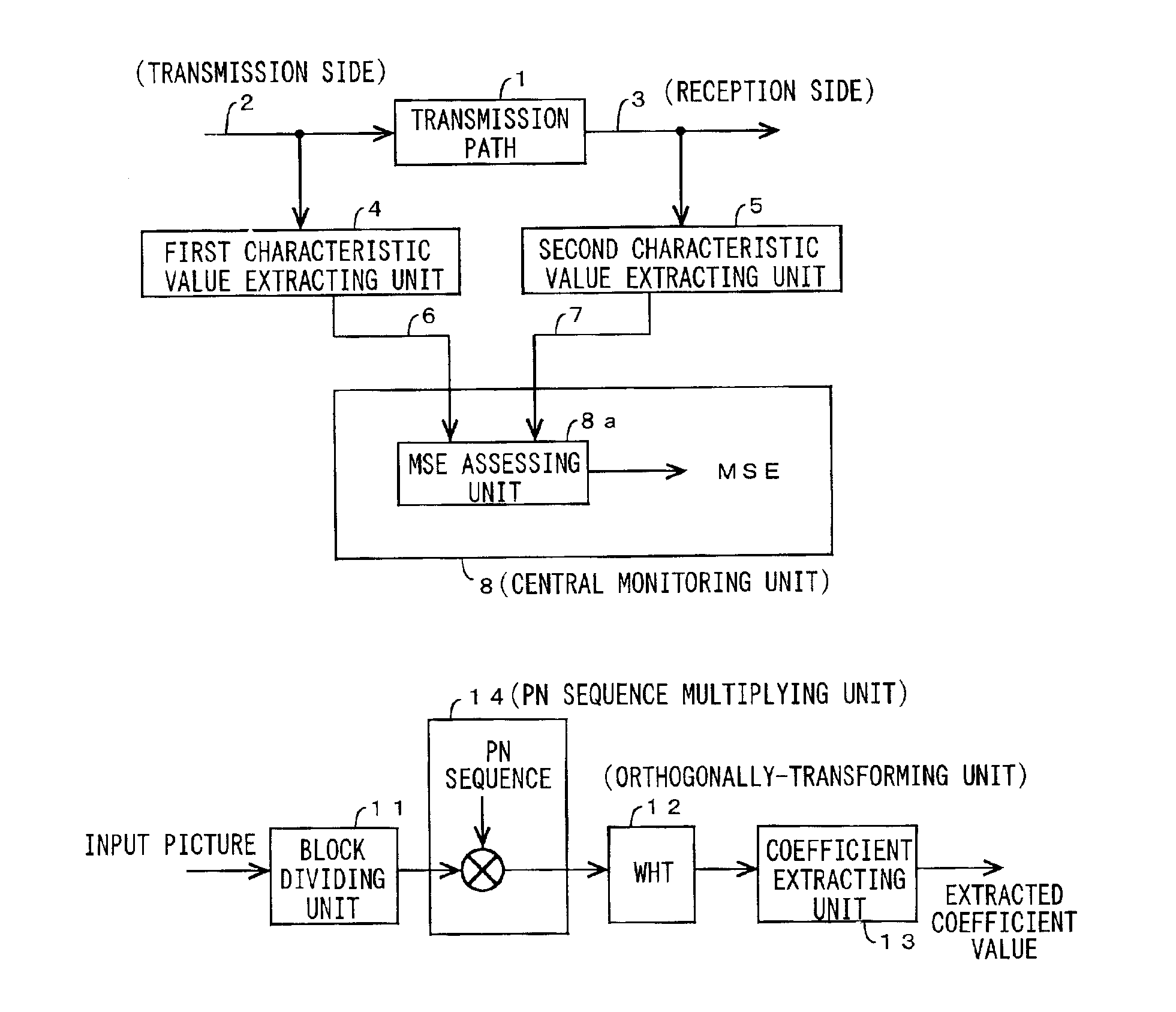
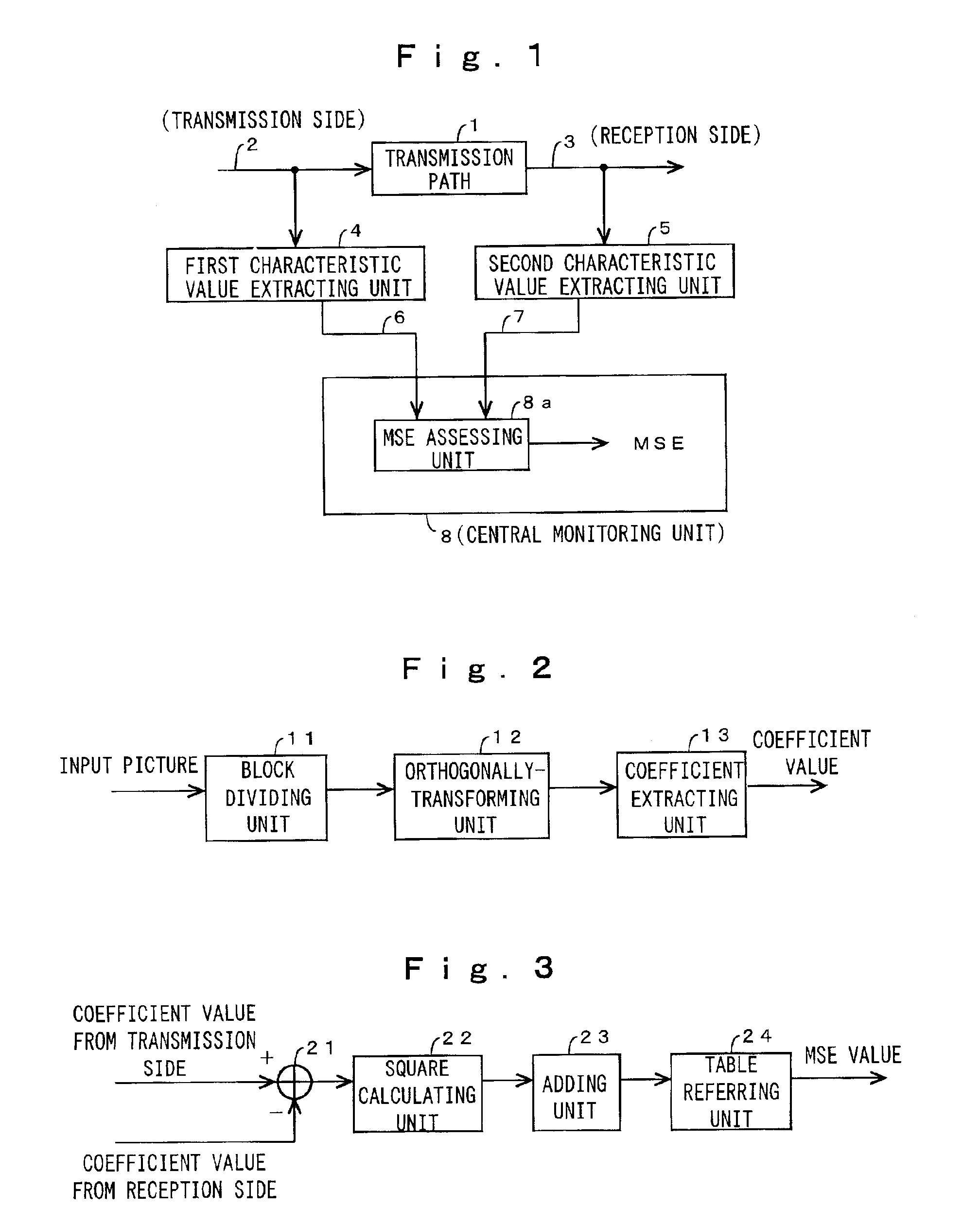
[0035]The present invention will be described below in detail with reference to the drawings. FIG. 1 is a block diagram showing the schematic arrangement of the present invention applied to a system (referred to as a picture transmission chain) in which a plurality of transmission processing devices are connected in series to a transmission path. FIG. 1 shows an arrangement of a portion of the picture transmission chain.

[0036]In FIG. 1, a picture or video picture is transmitted from a transmission side 2 to a reception side 3 through a transmission path 1. A first characteristic value extracting unit 4 extracts the characteristic value of the picture transmitted from the transmission side 2. In contrast, a second characteristic value extracting unit 5 extracts the characteristic value of the picture received on the reception side 3. The characteristic values extracted by the first and second characteristic value extracting units 4 and 5 are supplied to a central monitoring unit 8 th...

second embodiment

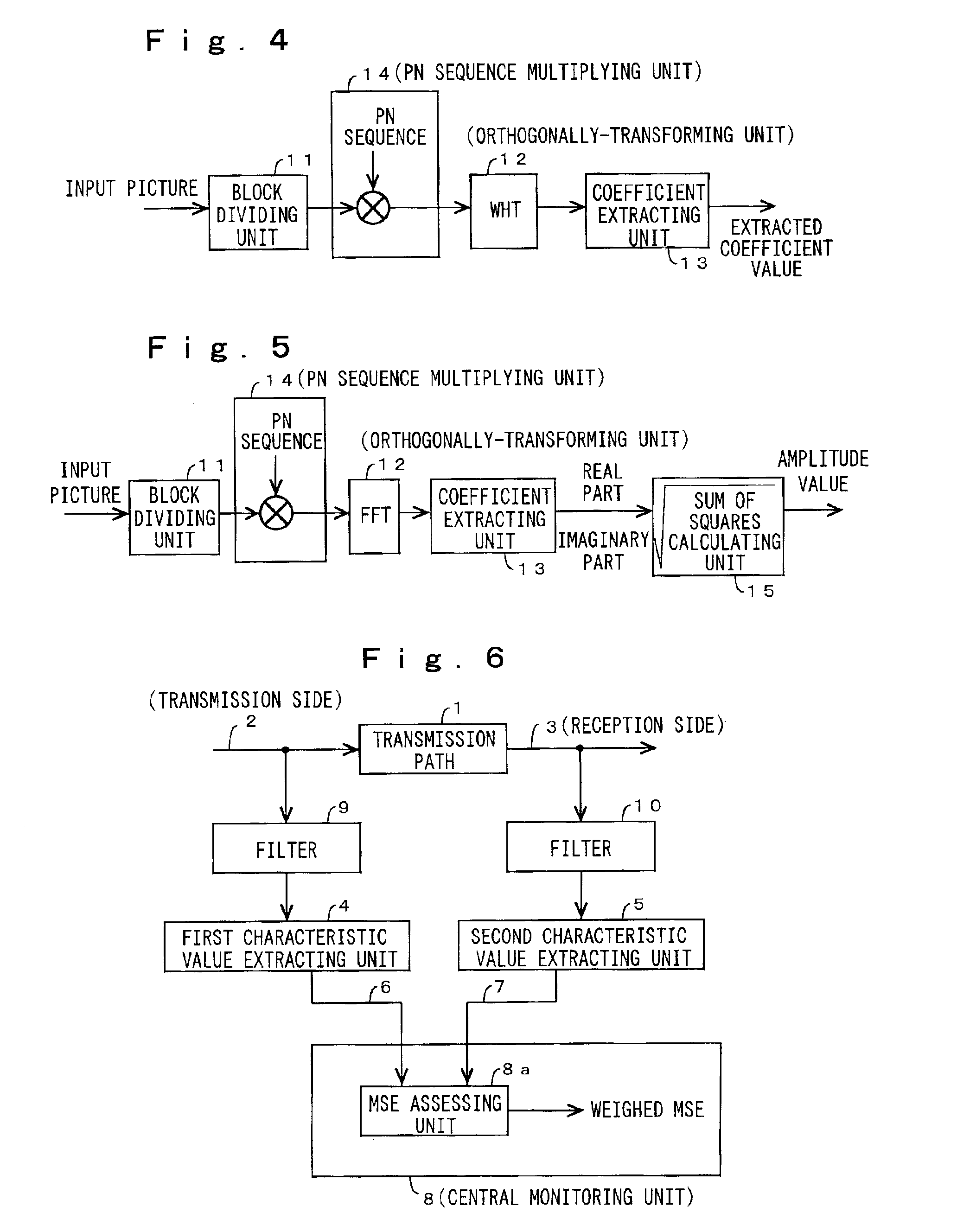
[0054]Next, the present invention will be described with reference to FIG. 4. FIG. 4 is a block diagram showing a specific arrangement of the first and second characteristic value extracting units 4 and 5.

[0055]In FIG. 4, first, an input picture is supplied to a block dividing unit 11 and divided into blocks. However, the “block” is defined as described above. Next, the signals in the blocks are subjected to spectrum spreading in a PN sequence multiplying unit 14. That is, the blocks are multiplied by a PN sequence. The PN sequence may be any arbitrary sequence of numbers in which +1 and −1 are generated at random (such as +1, +1, −1, +1, −1, −1, +1, −1, +1, . . . ). Thereafter, the resultant blocks are subjected to Walsh Hadamard transformation (hereinafter, abbreviated as “WHT”). In a picture G having a block size of, for example, 8×8, the WHT is shown by α as shown below.

α=UGU U=[111111111111-1-1-1-111-1-1-1-11111-1-111-1-11-1-111-1-111-1-11-111-11-11-1-11-111-11-11-11-1]

α shows ...

third embodiment

[0060]Next, the present invention will be described with reference to FIG. 5. FIG. 5 is a block diagram showing a third specific arrangement of the first and second characteristic value extracting units 4 and 5.

[0061]FIG. 5 is different from FIG. 4 in that a Fourier transformation FFT is used as an orthogonally-transforming unit 12 and that a sum of squares calculating unit 15 is disposed behind a coefficient extracting unit 13. In FIG. 5, the same reference numerals as those used in FIG. 4 denote the same components or similar components.

[0062]A first feature of the third embodiment resides in that the Fourier transformation FFT is used as the orthogonally-transforming unit 12. The Fourier transformation FFT is a most precise and appropriate method of transformation physically in the meaning of frequency spectrum. This is a merit of using the Fourier transformation as the orthogonal transformation. Note that, to realize the third embodiment, it is appropriate to make use of high sp...


PUM


Abstract

A first characteristic value extracting unit extracts a characteristic value from a picture transmitted from a transmission side, and a second characteristic value extracting unit extracts a characteristic value from a picture received on a reception side. These extracted characteristic values are supplied to a central monitoring unit through low speed lines, respectively. In the central monitoring unit, an MSE (mean square error) is assessed from the data by an MSE assessing unit. The first and second characteristic value extracting units divide an input picture into blocks, subject the blocks to an orthogonal transformation, or subject the blocks to PN sequence multiplication before the orthogonal transformation, and extract and output orthogonal transformation coefficients. The MSE assessing unit determines the differences between corresponding coefficients on the transmission side and the reception side and squares the differences, adds the squared differences for every coefficients or every blocks, and assess an MSE based on the added values referred to a table. With this operation, the MSE can be effectively assessed using a smaller amount of extracted data (accordingly, slower speed lines can be used in the central monitoring unit).

Description

BACKGROUND OF THE INVENTION[0001]1. Field of the Invention[0002]The present invention relates to an apparatus for monitoring quality of a picture in transmission that is preferable to collectively remote-monitor at a center the picture or video picture quality at a plurality of transmission processing positions disposed in sequence in a transmission path.[0003]2. Description of the Related Art[0004]As a conventional method of automatically monitoring and assessing video picture quality, there are available (1) a method of comparing a processed picture with its original picture, (2) a method of assessing picture quality based on only a processed picture, and (3) a method of comparing the characteristic value of an original picture with that of a processed picture.[0005]An example of the method (1) is disclosed in detail in, for example, the following document. T. Hamada. et al. “Picture quality assessment system by three-layered bottom-up noise weighing considering human visual perce...

Claims


Application Information

Patent Timeline
IPC IPC(8): H04N17/00
CPCH04N17/00
Inventor KAWADA, RYOICHISUGIMOTO, OSAMUWADA, MASAHIROMATSUMOTO, SHUICHI
Owner KDDI CORP
Why Eureka
Try Eureka