Organic field effect transistor and method of manufacturing the same

a technology of organo-electric transistors and transistors, which is applied in the direction of thermoelectric device junction materials, semiconductor devices, electrical equipment, etc., can solve the problems of deterioration of the element characteristics, the gradual change of the fet characteristics or on/off ratio, and the insatiable on/off ratio of current between the source and the drain or improvement of the gate insulating film

Inactive Publication Date: 2008-05-13
PANASONIC CORP
View PDF22 Cites 18 Cited by
  • Summary
  • Abstract
  • Description
  • Claims
  • Application Information

AI Technical Summary

Benefits of technology

[0015]Accordingly, the present invention is made up to solve the above-mentioned problems and it is an object of the invention to provide an organic field effect transistor in which element characteristics and stability are improved to achieve a long life span.
[0017]According to the above-mentioned structure, since the charge injection layer formed of an inorganic material is interposed, the charge injection can be easily carried out, a driving voltage can decrease, and stable element characteristics and improved reliability can be achieved. The exact reason why these are possible is unclear but the followings can be considered as a possible answer. That is, in order to easily inject the hole serving as the carrier, the charge injection layer made of an inorganic material is interposed between the channel and the source / drain electrode so that an energy level of the charge injection layer has an average value of an energy level of the channel and an energy level of the source / drain electrode. Typically, in a case in which the inorganic material is used, it is possible to allow it to have a middle energy level by using a p-typed semiconductor as a semiconductor.
[0019]According to the above-mentioned structure, since the buffer layer is interposed, it is possible to improve the stability and reliability of the element characteristics. The exact reason why these are possible is unclear but the followings can be considered as a possible answer. That is, by giving and receiving the charge, oxidation-reduction reaction occurs repeatedly on the interface between the organic semiconductor layer and the source / drain electrode, and thus the source electrode and drain electrode are easily deteriorated. On the other hand, according to the structure in which the buffer layer made of the inorganic material is interposed on the interface between the organic semiconductor layer and the source / drain electrode, adherence is improved due to the presence of the buffer layer, electrodes hardly undergo deterioration and the characteristic change is less after the element is manufactured, and thus an organic field effect transistor with stability and a long life span is expected to be achieved. Considering the fact that an organic semiconductor is vulnerable to reduction reaction, a buffer layer made of an inorganic material is interposed between the organic semiconductor layer and electrodes in order to prevent the organic semiconductor layer from undergoing reduction, thus effectively preventing deterioration from being generated. In addition, making a condition where the organic semiconductor layer hardly undergoes reduction reaction by interposing a stable inorganic material (for example, a nitride) or an oxygen-rich-inorganic material (for example, oxide) between the organic semiconductor layer and the electrodes is considered to one reason. This is especially effective for the drain electrode which the reduction reaction easily occurs and which is an electron supply electrode or a hole discharging electrode.
[0020]In addition, the presence of the buffer layer can also prevent concentration of carriers and deterioration.
[0021]Furthermore, when platinum or gold is used for an electrode, it serves as a catalyst for the organic semiconductor layer to promote the reaction of the organic semiconductor layer to cause deterioration. However, the deterioration occurred on the interface can be prevented by interposing the buffer layer.

Problems solved by technology

However, even in the above-mentioned organic field effect transistors, the ON / OFF ratio of current between the source and the drain or improvement of a gate insulating film and characteristic stability that is a condition to be met for practical use are not satisfactory.
When the element characteristics are unstable, the FET characteristics or ON / OFF ratio are gradually changed from the time when the element is fabricated and are deteriorated in proportion to multiplication of power supply time and amount of power.
Even in case in which no power is supplied into the element, its element characteristics gradually deteriorate due to oxygen or moisture in the atmosphere.
Therefore, the deterioration of element characteristics makes it difficult for the organic field effect transistor to be in practical use.

Method used


Image

  • Organic field effect transistor and method of manufacturing the same
  • Organic field effect transistor and method of manufacturing the same
  • Organic field effect transistor and method of manufacturing the same

Examples


first embodiment

[0125]The present invention has the structure that at least one of a source electrode and a drain electrode come in contact with an organic semiconductor film made of an organic semiconductor material with a charge injection layer made of an inorganic material interposed to achieve stable element characteristics.

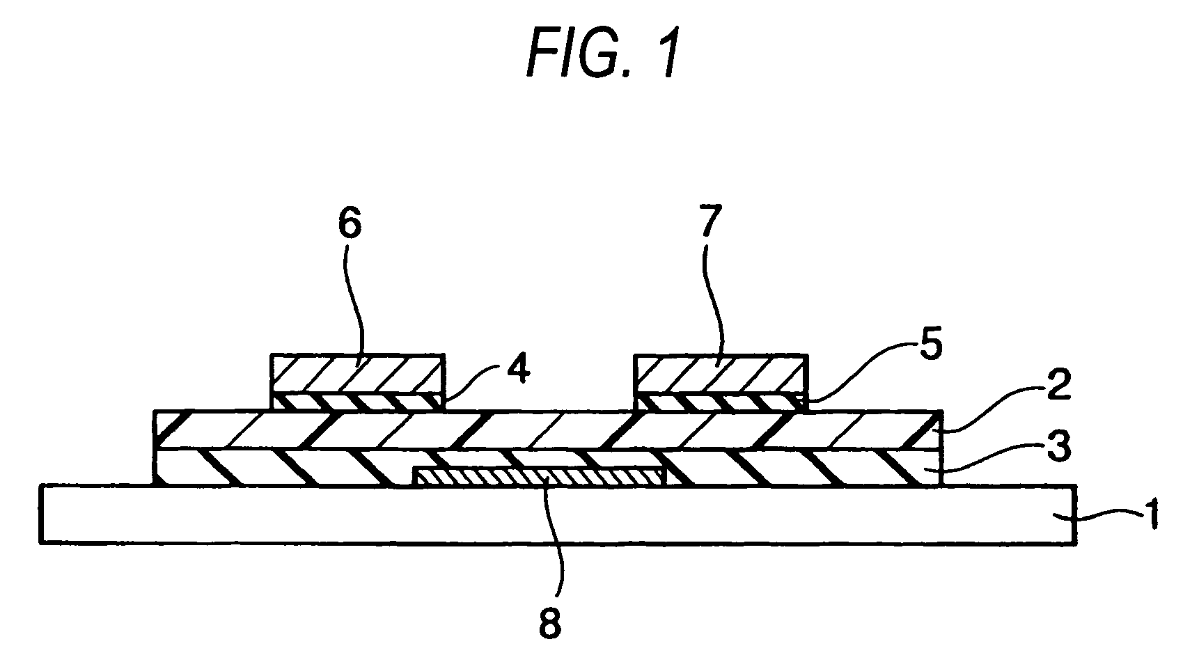
[0126]FIG. 1 shows the structure of an organic field effect transistor. It has the stack structure where source and drain electrodes 6 and 7 and a gate electrode 8 are formed so as to be opposite to each other with an organic semiconductor film 2 formed above a substrate 1 interposed. A source-side charge injection layer 4 and a drain-side charge injection layer 5 are formed between the source electrode 6 and the organic semiconductor film 2 and between the drain electrode 7 and the organic semiconductor film 2, respectively.

[0127]According to the invention having the above-mentioned structure, stable element characteristics can be achieved and an organic field effect transi...

example 1

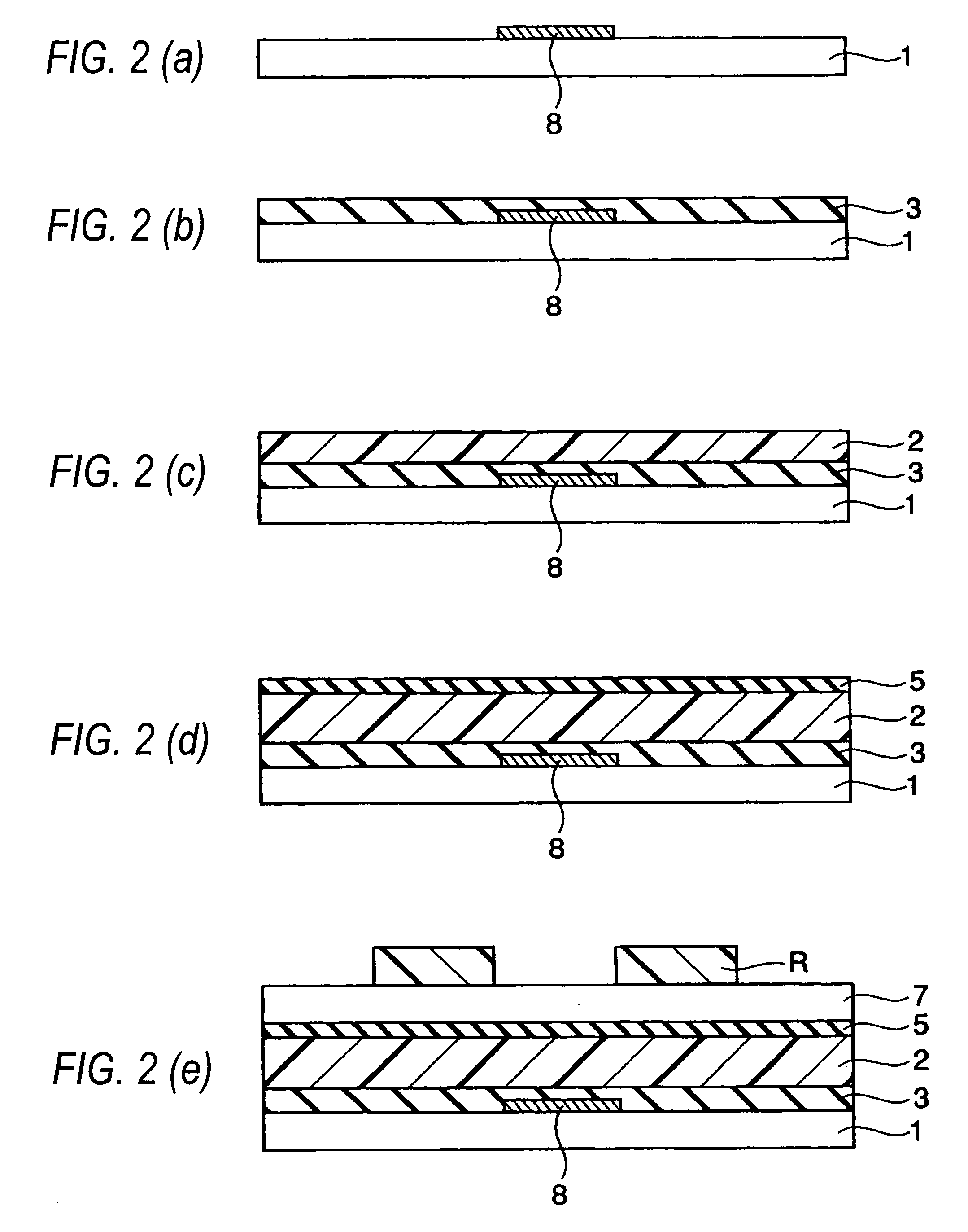
[0173]Next, a first example according to the present invention will be described below. First, an aluminum (Al) thin film is formed on a substrate 1 made of glass by about 500 nm thickness under 0.27 mPa (2×10⁻⁶ Torr) using a resistant heat deposition apparatus and then patterned using a photolithography method to form a gate electrode 8 (FIG. 2(a)).

[0174]Next, a polyimide film is deposited thereon to form a gate insulating film 3 (FIG. 2(b)), polyphenylenevinylene is spin coated thereon and then subject to a heat treatment to form a p-type organic semiconductor film 2 containing polyphenylenevinylene as a main component (FIG. 2(c)).

[0175]Next, the sample is divided into two samples. A source-side charge injection layer 4 and a drain-side charge injection layer 5 are formed on one sample (hereinafter, referred to as a present sample) and not formed on the other sample (hereinafter, referred to as a comparative sample).

[0176]On the present sample, as shown in FIG. 2(d), as the source...

second embodiment

[0181]Next, a second embodiment according to the present invention will be described below. According to the first embodiment, the source-side charge injection layer 4 and the drain-side charge injection layer 5 have the same patterns as the source electrode 6 and the drain electrode 7, respectively. However, the second embodiment, as shown in FIG. 4, has a structure where the source-side charge injection layer 4 and the drain-side charge injection layer 5 are integrally formed as a charge injection layer 14S formed to cover the entire surface of the organic semiconductor film 12. For the operation thereof, similar to the first embodiment, the charge injection effect can be obtained between the organic semiconductor film 12 and the source and drain electrodes 16 and 17. However, since the charge injection layer 14S covers the entire surface of the organic semiconductor film 12, air is prevented from permeating into the organic semiconductor film vulnerable to moisture and heat, thus...


PUM


Abstract

To provide an organic field effect transistor with stable characteristics and a long life span, an organic field effect transistor includes a gate electrode 8 formed on an organic semiconductor film 2 made of an organic semiconductor material with a gate insulating film 3 interposed therebetween; and a source electrode 6 and a drain electrode 7 provided so as to come in contacts with the organic semiconductor film with the gate electrode 8 interposed therebetween. At least one of the source electrode 6 and the drain electrode 7 is formed in contact with the organic semiconductor film 2 with charge injection layers 4 and 5 made of an inorganic material interposed therebetween.

Description

BACKGROUND OF THE INVENTION[0001]1. Field of the Invention[0002]The present invention relates to an organic field effect transistor and a method of manufacturing the same and more particularly, to an organic field effect transistor with a long life span by employing a channel made of an organic semiconductor material.[0003]2. Description of the Related Art[0004]An organic field effect transistor using an organic semiconductor has been researched as a substitute for a transistor made of an inorganic material, such as silicone, which has been widely used, for example, an amorphous silicone thin film transistor used for switching control in a liquid crystal display device, and recently, a device with performance as good as the amorphous silicone thin film transistor has been suggested.[0005]The organic field effect transistor has several characteristics when compared to a field effect transistor (hereinafter, referred to as an inorganic field effect transistor) now widely in use based ...

Claims


Application Information

Patent Timeline
Patent Type & Authority Patents(United States)
IPC IPC(8): H01L51/10H01L51/00H01L51/05H01L21/00H01L35/24
CPCH01L51/0021H01L51/0541H01L51/0545H01L51/105H10K71/60H10K10/464H10K10/84H10K10/466
Inventor YATSUNAMI, RYUICHISAKANOUE, KEI
Owner PANASONIC CORP
Why Eureka
Try Eureka