Arrangement of a gear shift fork in a transmission

a gear shift fork and transmission housing technology, which is applied in the direction of mechanical control devices, instruments, process and machine control, etc., can solve the problems of increased loading of the shift rod and the shift rocker, no longer optimal overlap, etc., and achieve the effect of reducing sliding blocks, improving the engagement of the shift rocker in the shift rod, and improving friction for

Inactive Publication Date: 2010-05-13
ZF FRIEDRICHSHAFEN AG
View PDF16 Cites 10 Cited by
  • Summary
  • Abstract
  • Description
  • Claims
  • Application Information

AI Technical Summary

Benefits of technology

[0006]The purpose of the present invention is to design an arrangement of a shift rocker of the type described at the start, in such manner that wear of the sliding blocks is reduced and engagement of the sliding blocks in the sliding sleeve and the engagement of the shift rocker in the shift rod are improved.
[0007]According to the invention it is provided that the shift rocker rests its weight on the shift rod and no longer—as in the prior art—on the sliding sleeve. By virtue of its pivot bearing on pivot pins the shift rocker can move freely in the vertical direction, so that the weight of the shift rocker can be supported on the shift rod by a supporting element arranged on the shift rocker. This has the advantage that the upper sliding block is relieved from the weight of the shift rocker, so that the friction force between the upper sliding block and the base of the groove in the sliding sleeve is reduced. This improves the efficiency of the transmission. The upper sliding block rests on the groove bottom of the sliding sleeve only under its own weight. Moreover, another advantage is that the supporting element rests at all times against the shift rod on a corresponding contact surface, so that optimum engagement is achieved during transfer of the shifting movement from the shift rod to the shift rocker. In addition, the overlap between the lower sliding block and the annular groove of the sliding sleeve is improved.
[0008]In a preferred design, the shift rod has a groove opening downward, in which a coupling element of the shift rocker engages. The supporting element also arranged on the shift rocker, rests on a contact surface against the upper circumference of the shift rod, and so supports the shift rocker on the shift rod. This division of functions has the advantage that the shifting force transmission takes place with less friction.

Problems solved by technology

Problems can arise if the pivot axis is arranged not horizontally but vertically—because in relation to the engagement of the sliding blocks in the annular groove of the sliding sleeve various situations can exist.
This has the disadvantage that the upper sliding block is continually subjected to wear and the lower sliding block slips out of the annular groove (downward), so that the overlap is no longer optimal.
Accordingly, as the upper sliding block becomes progressively more worn the play in the vertical direction between the shift rocker and the shift rod also increases, which reduces the overlap and results in increased loading of the shift rod and the shift rocker.

Method used


Image

  • Arrangement of a gear shift fork in a transmission
  • Arrangement of a gear shift fork in a transmission
  • Arrangement of a gear shift fork in a transmission

Examples


Embodiment Construction

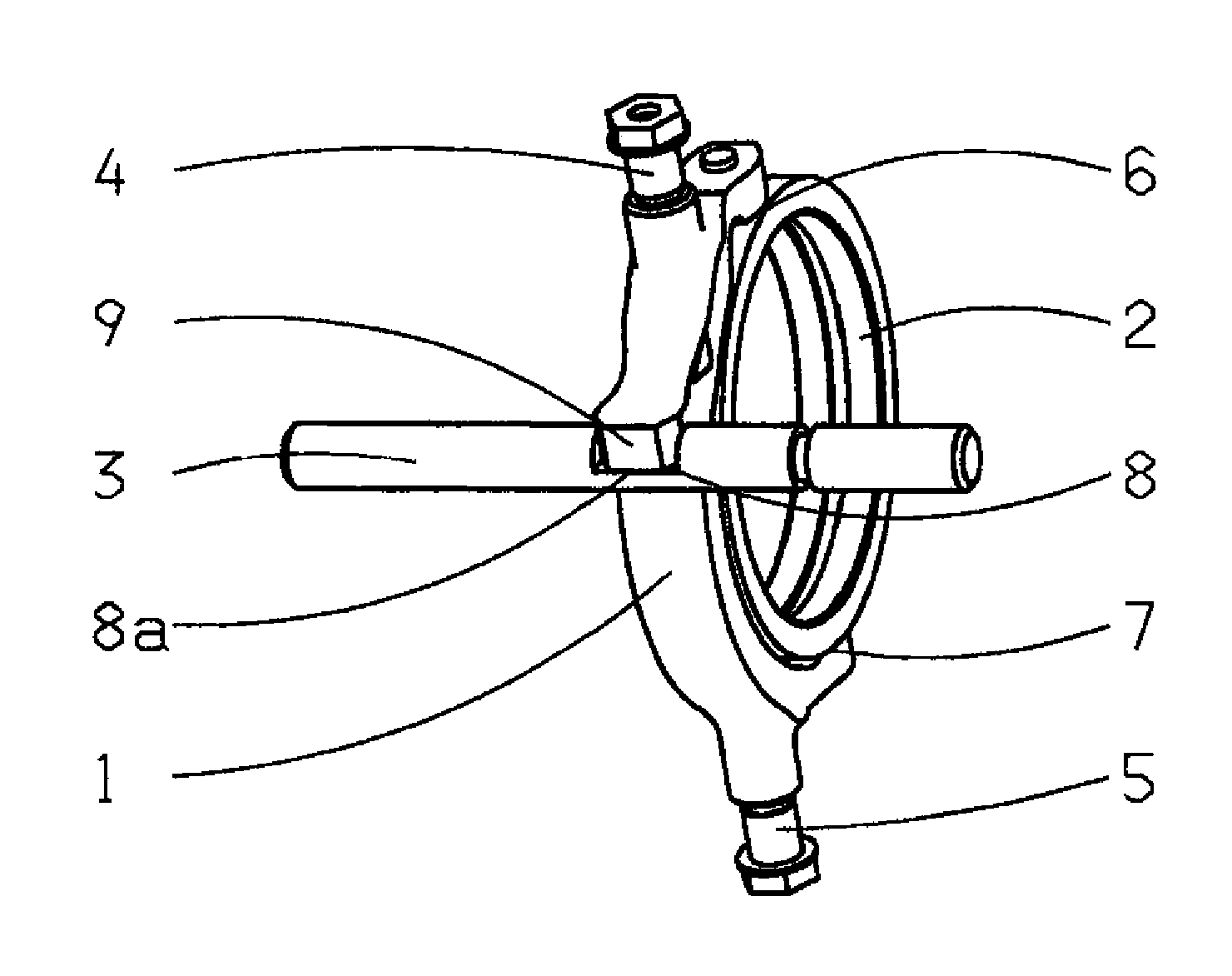
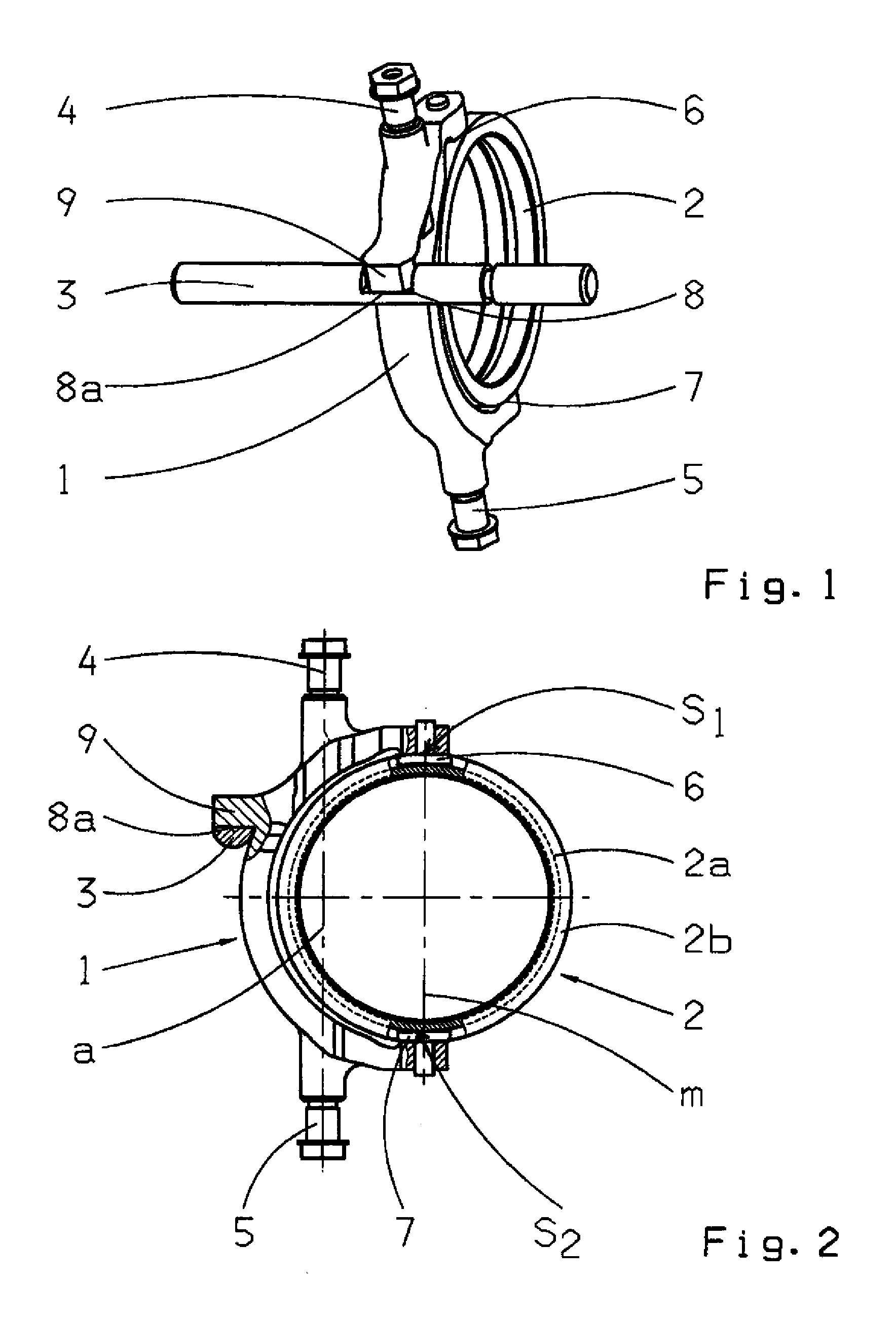
[0013]FIG. 1 shows a perspective representation of a shift rocker 1, a sliding sleeve 2 and a shift rod 3, arranged in a housing of a manual transmission (not shown). The shifting means 1, 2, 3 shown serve to carry out gearshifts, during which the sliding sleeve is pushed axially over a shaft (not shown) to engage in an adjacent gearwheel (not shown). The shift rocker 1 is mounted to pivot on two pins 4, 5 fixed on the housing, the pivot axis defined by the longitudinal axes of the said pins being orientated vertically. The shift rocker 1 engages with two sliding blocks, an upper sliding block 6 and a lower sliding block 7, in an annular groove (not indexed) of the sliding sleeve 2. The shift rod 3 is mounted fixed on the housing—this is not shown—and in the area of the shift rocker 1 has a groove 8 open upward, in which a supporting element 9 arranged on the shift rocker 1 engages. Together with the shift rod 3 the supporting element 9 forms a coupling joint so that when the shift ...


PUM


Abstract

An arrangement of a shift rocker (1), in a transmission housing, comprising a sliding sleeve (2) and a shift rod (3). The shift rocker (1) is mounted to pivot relative to the housing about a pivot axis, can be actuated by the shift rod (3), and engages with an annular groove of the sliding sleeve (2), via sliding blocks (6, 7). The pivot axis of the shift rocker is substantially vertically orientated and the shift rocker (1) has at least one supporting element (9), located outside the vertically orientated pivot axis, which rests on the shift rod (3).

Description

[0001]This application is a National Stage completion of PCT / EP2008 / 052743 filed Mar. 7, 2008, which claims priority from German patent application serial no. 10 2007 013 929.4 filed Mar. 23, 2007.FIELD OF THE INVENTION[0002]The invention concerns an arrangement of a shift rocker in a transmission housing.BACKGROUND OF THE INVENTION[0003]Shift rockers are known shift elements for carrying out gearshifts in a manual transmission. The shift rocker is curved or fork-shaped and is mounted to pivot relative to the transmission housing. It engages with sliding blocks in an annular groove of a shifting or sliding sleeve, which shifts the desired gear. The shift rocker is actuated by a shift rail or shift rod arranged to move longitudinally in the transmission housing and connected to the shift rocker by a coupling joint. This causes the shift rocker to pivot in one direction or the other.[0004]From DE 43 42 957 A1 by the present applicant a shifting mechanism with a shift rocker of this ty...

Claims


Application Information

Patent Timeline
Patent Type & Authority Applications(United States)
IPC IPC(8): F16H63/32
CPCF16H63/32Y10T74/20183F16H2063/325F16H2063/321
Inventor HOERING, GERHARDMILLER, MARTIN
Owner ZF FRIEDRICHSHAFEN AG
Why Eureka
Try Eureka