Driving method and driving device for standing-wave-type ultrasonic actuator

a driving device and ultrasonic actuator technology, applied in piezoelectric/electrostrictive/magnetostrictive devices, piezoelectric/electrostriction/magnetostriction machines, electrical apparatus, etc., can solve the problems of affecting the operation of the driving body. , the effect of reducing the friction between the vibrator and the driven body

Inactive Publication Date: 2008-07-10
OLYMPUS CORP
View PDF2 Cites 9 Cited by
  • Summary
  • Abstract
  • Description
  • Claims
  • Application Information

AI Technical Summary

Benefits of technology

[0007]However, in the traveling-wave-type ultrasonic motor disclosed in Japanese Unexamined Patent Application, Publication No. 2002-199749, because the driving torque during activation and stopping is small, the frictional force between a vibrator and a driven body is consequently reduced. When such an activation method and driving method are applied to a standing-wave-type ultrasonic motor, there is a problem in that, during activation, the driven body falls due to the effect of gravity because the static friction between the vibrator and the driven body is reduced. In addition, when stopping driving, there is also a problem in that it takes time for the driven body to stop moving if the inertial force is large.

Problems solved by technology

When such an activation method and driving method are applied to a standing-wave-type ultrasonic motor, there is a problem in that, during activation, the driven body falls due to the effect of gravity because the static friction between the vibrator and the driven body is reduced.
In addition, when stopping driving, there is also a problem in that it takes time for the driven body to stop moving if the inertial force is large.

Method used


Image

  • Driving method and driving device for standing-wave-type ultrasonic actuator
  • Driving method and driving device for standing-wave-type ultrasonic actuator
  • Driving method and driving device for standing-wave-type ultrasonic actuator

Examples


Embodiment Construction

[0040]A driving method and driving device of a standing-wave-type ultrasonic actuator (hereinafter simply referred to as “ultrasonic actuator”) according to an embodiment of the present invention are described below with reference to the drawings.

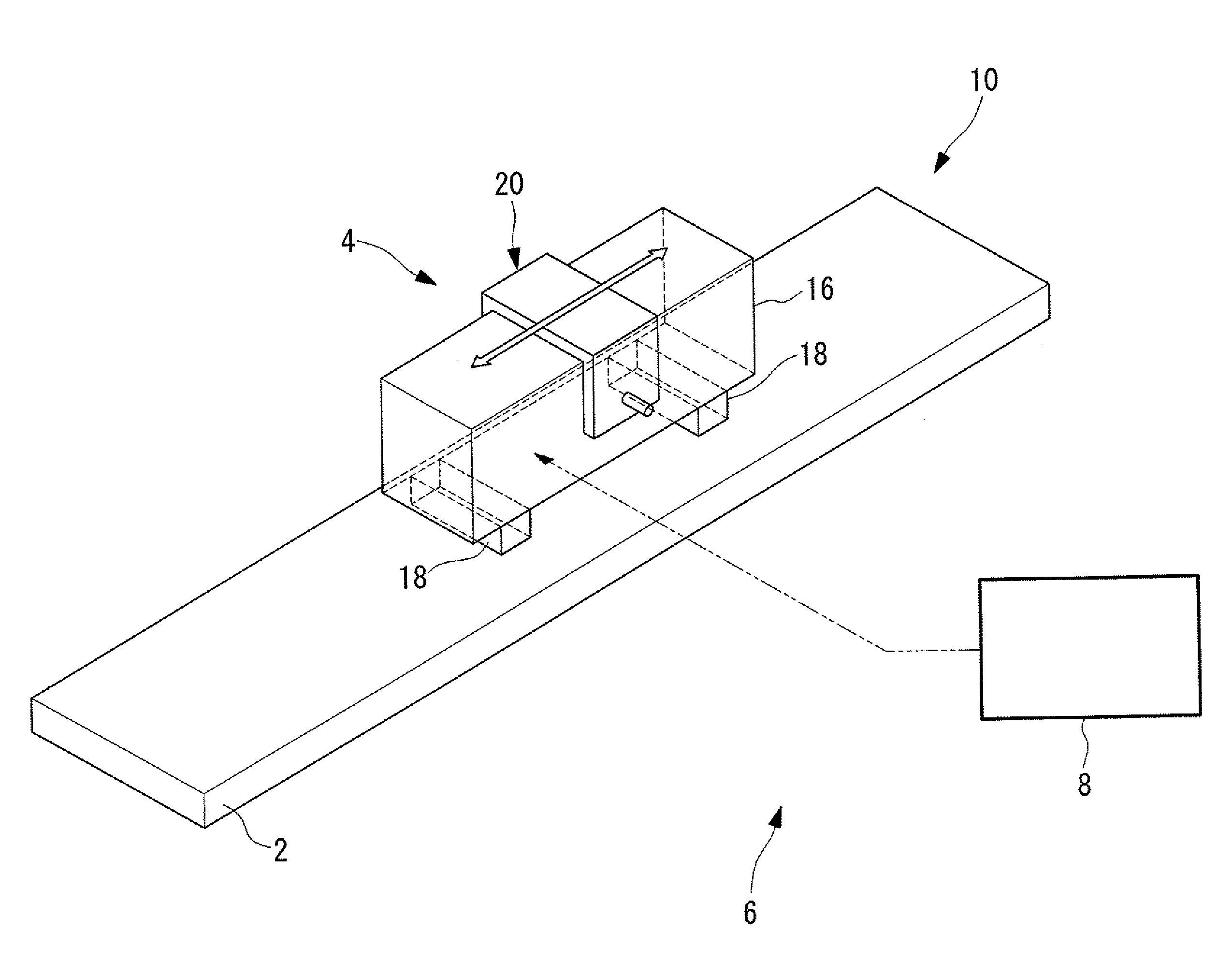
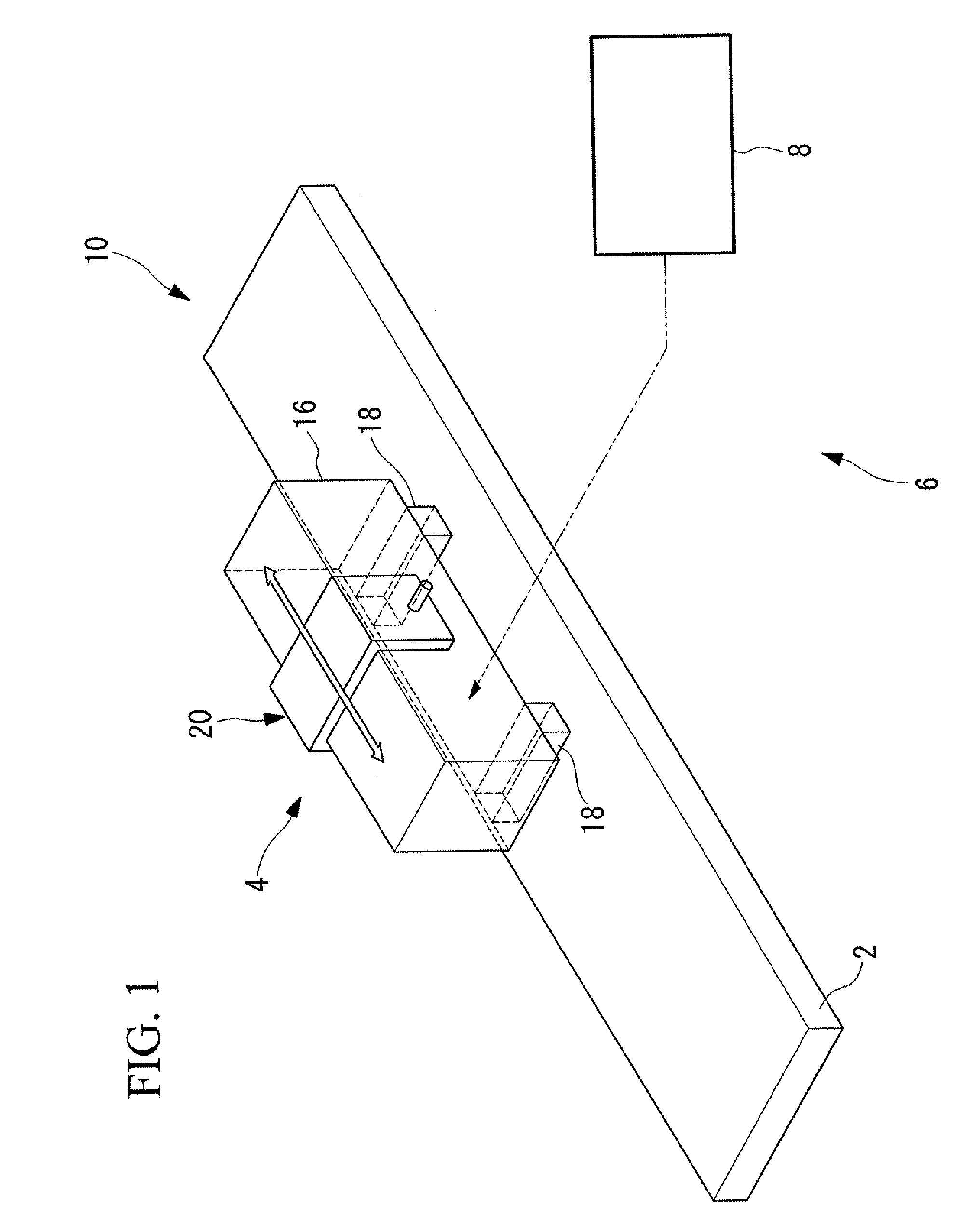
[0041]As shown in FIG. 1, an ultrasonic actuator 10 according to this embodiment includes a driven body 2 and an ultrasonic vibrator 4 disposed in contact with the driven body 2. The ultrasonic vibrator 4 is pressed against the driven body 2 with a prescribed pressing force by pressing part, which is not shown in the drawing. An ultrasonic-actuator system 6 according to this embodiment includes the ultrasonic actuator 10 described above and a driving device 8 for driving the ultrasonic actuator 10.

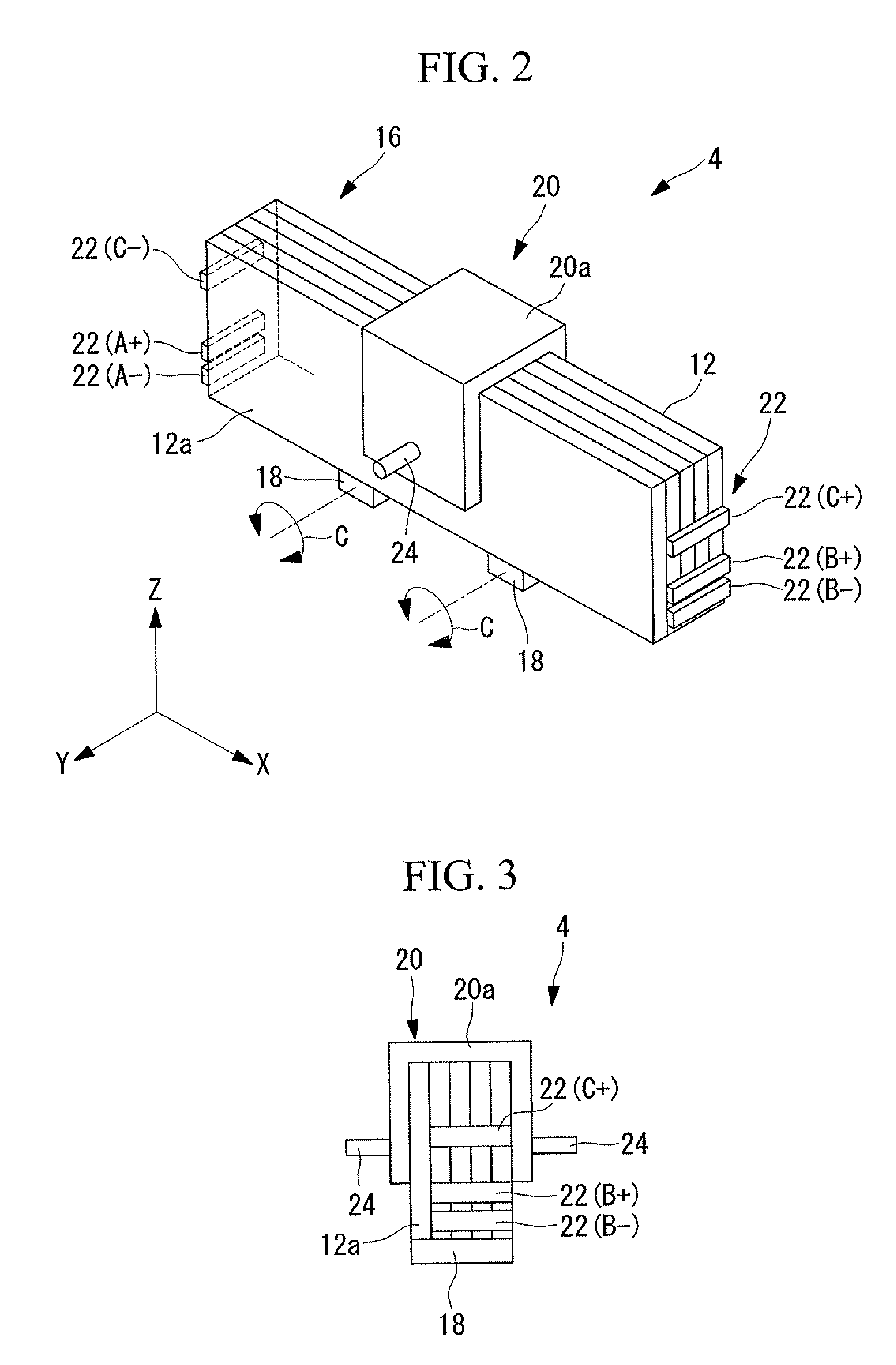
[0042]As shown in FIGS. 2 and 3, the ultrasonic vibrator 4 includes, for example, a rectangular-block-shaped piezoelectric layered member 16, two friction-contact members 18, and a vibrator holding member 20. The piezoelectric layered member 16 is...


PUM


Abstract

The invention provides a driving method and driving device for a standing-wave-type ultrasonic actuator which can prevent falling of and eliminate unstable motion of a driven body during activation, and which can shorten the time for the driven body to stop moving when driving is to be stopped. In the driving method for a standing-wave-type ultrasonic actuator, by generating a longitudinal vibration and a flexural vibration in an ultrasonic vibrator, a substantially elliptical vibration is produced at a friction-contact member of the ultrasonic vibrator, and with a frictional force of the elliptical vibration serving as a propulsive force, the ultrasonic vibrator and a driven body in contact with the ultrasonic vibrator are made to move relative to each other. The longitudinal vibration is excited at activation time, and the flexural vibration is excited thereafter.

Description

BACKGROUND OF THE INVENTION[0001]1. Field of the Invention[0002]The present invention relates to a driving method and a driving device for a standing-wave-type ultrasonic actuator.[0003]This application is based on Japanese Patent Application No. 2007-000770, the content of which is incorporated herein by reference.[0004]2. Description of Related Art[0005]Recently, ultrasonic motors have been drawing attention as a new type of motor replacing electromagnetic motors. Ultrasonic motors have the following advantages over known electromagnetic motors:1) Ultrasonic motors are capable of high torque without using gears;2) Ultrasonic motors have holding force when powered off;3) Ultrasonic motors have high resolution;4) Ultrasonic motors are quiet; and5) Ultrasonic motors do not generate magnetic noise and are unaffected by noise.[0006]Ultrasonic motors are classified into traveling-wave-type ultrasonic motors and standing-wave-type ultrasonic motors based on the principle of wave propagat...

Claims


Application Information

Patent Timeline
Patent Type & Authority Applications(United States)
IPC IPC(8): H01L41/09H02N2/00
CPCH02N2/004H02N2/06H02N2/026H02N2/062
Inventor OKADA, JUNJI
Owner OLYMPUS CORP
Why Eureka
Try Eureka