Self-cleaning filter

a filter and self-cleaning technology, applied in the field of self-cleaning air filters and cooling systems, can solve the problems of limited equipment surface area, insufficient simple convective approach to expels equipment heat, and large installation of new equipment, and achieve the effect of less complex and less expensiv

Inactive Publication Date: 2005-01-11
SPIRENT COMM
View PDF11 Cites 14 Cited by
  • Summary
  • Abstract
  • Description
  • Claims
  • Application Information

AI Technical Summary

Benefits of technology

By utilizing a single air flow path for both the equipment cooling and cleaning of the filter, the self-cleaning filter in accordance with exemplary embodiments of the present invention is less complex and less expensive than known self-cleaning systems.

Problems solved by technology

Additionally, a significant portion of new equipment is now installed at remote terminals that have relatively dirty environments and that are subject to relatively more severe temperature extremes, for example, −40° C. to +65° C. Under these more harsh conditions, the simple convective approach to expelling equipment heat is inadequate.
However, the available equipment surface area is limited, so that even this approach to heat dissipation can be inadequate.
This approach results in the construction of a somewhat complex equipment enclosure with a mechanism to separately move the air interior to and exterior to the equipment enclosure.
Accordingly, although current equipment standards permit a fan in conjunction with a filter and a specified maintenance interval, in practice, the filter will rarely be changed without regard to the maintenance interval specified, unless there is an equipment failure.
However, such systems are relatively complex and expensive.

Method used


Image

  • Self-cleaning filter
  • Self-cleaning filter
  • Self-cleaning filter

Examples


Embodiment Construction

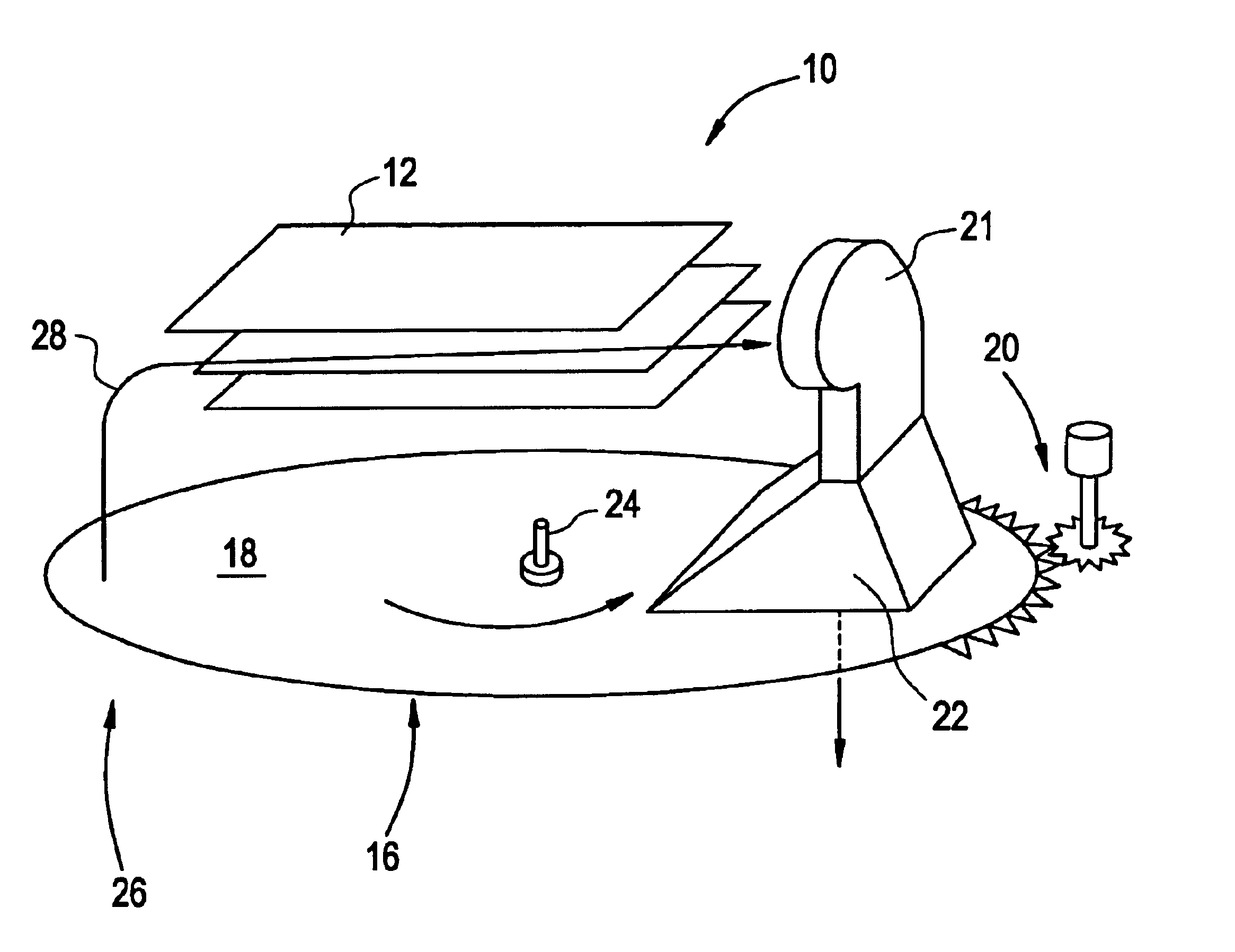
The present invention relates to a self-cleaning filter and cooling system used to cool the interior of an equipment enclosure with ambient air. In accordance with an exemplary embodiment of the present invention, a single air flow path is used both for cooling the interior of the equipment enclosure and for cleaning the filter. Consequently, the self-cleaning filter and cleaning system according to exemplary embodiments is less complex and expensive than known self-cleaning systems.

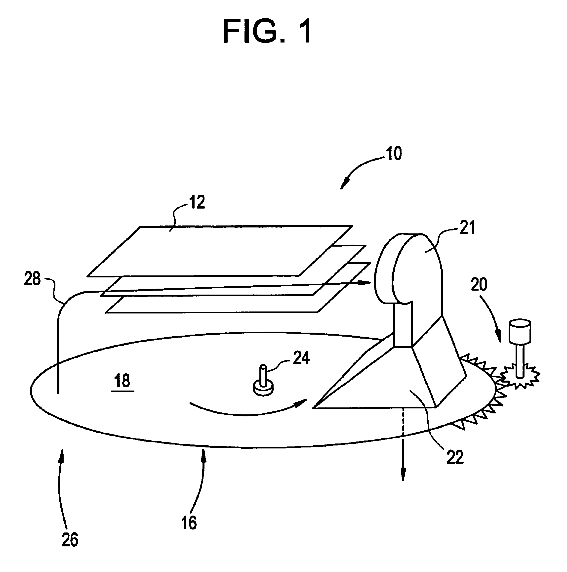
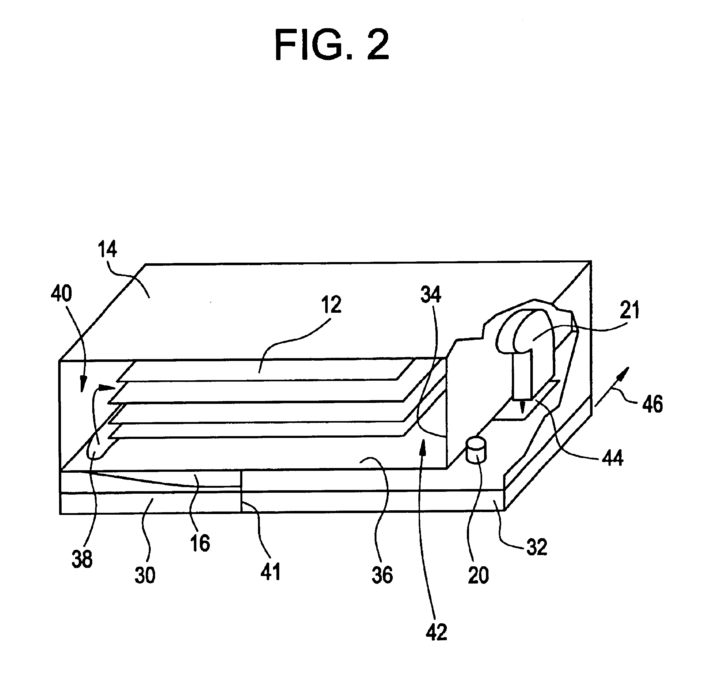
These and other aspects of the present invention will now be described in greater detail. An exemplary embodiment of the self-cleaning filter and cooling system is illustrated in FIGS. 1 and 2. In particular, FIG. 1 is a perspective view of a simplified diagram of a self-cleaning filter and cleaning system (shown with the equipment enclosure removed for purposes of clarity), in accordance with an exemplary embodiment of the present invention. FIG. 2 is a perspective view of a self-cleaning filter and coo...


PUM

PropertyMeasurementUnit
temperatureaaaaaaaaaa
particle sizeaaaaaaaaaa

Abstract

A self-cleaning filter and cooling system are disclosed for filtering ambient air used to cool the interior of an equipment enclosure. The system includes an enclosure for housing predetermined equipment to be cooled, the enclosure including an air intake port and an exhaust port. The system includes a blower for causing ambient air to be inducted into the enclosure through the air intake port and expelled from the exhaust port. The system also includes a filter that includes a predetermined filter media that covers the air intake port and the exhaust port. The filter moves relative to the air intake port and the exhaust port. The enclosure and blower are configured so as to create a single air flow path for equipment cooling and for discharging exhaust through the filter media to dislodge any particulate matter entrapped in the filter media.

Description

BACKGROUND1. Field of the InventionThe present invention relates to the field of filter cleaning systems. In particular, the present invention relates to a self-cleaning air filter and cooling system, preferably, for electronic equipment enclosures.2. Background InformationTelecommunications equipment can be installed in central office environments that are relatively clean and subject to limited temperature extremes. In response to these conditions, such telecommunications equipment was generally designed with relatively open, vertical printed circuit board orientations. These circuit boards were fitted into a card cage and utilized a baffle arrangement configured to promote convective flow of ambient air through the equipment to expel internally-generated heat that could otherwise damage the equipment. This approach was appropriate for the intended environment, required no maintenance, and provided good equipment life expectancies.Increasing emphasis has been placed on the control...

Claims


Application Information

Patent Timeline
Patent Type & Authority Patents(United States)
IPC IPC(8): B01D46/42H05K7/20B01D46/00B01D46/10
CPCB01D46/0056B01D46/0067H05K7/20181B01D46/10B01D2279/45B01D46/70
Inventor BAILEY, GEORGE R.
Owner SPIRENT COMM
Why Eureka
Try Eureka