Flexible switch and method for producing the same

Inactive Publication Date: 2005-01-11
YAZAKI CORP
View PDF19 Cites 78 Cited by
  • Summary
  • Abstract
  • Description
  • Claims
  • Application Information

AI Technical Summary

Benefits of technology

It is therefore an object of the present invention to provide a flexible switch and a method for producing the same which increases the installation range, and has a thin / lightweight design and a high degree of freedom for the configuration, and facilitates the mounting, and enables the space-saving, and enable to reflects the design change and model change of a machine and motor or a like.
In this configuration, the sheet cover member and depressing portion are changed by selecting the front sheet provided with the compatible external appearance portion, so that the variation-meeting range can be increased.

Problems solved by technology

Firstly, the overall structure is complicated, and the thickness of the main component members in the laminating direction is large, and most of the parts are made of rigid materials, and therefore there are encountered problems that it is difficult to achieve the thin / lightweight design of the switch and that the degree of freedom with respect to the configuration is almost zero.
Secondly, there is encountered a problem that a region where the switch is installed (or mounted) is limited to a portion where a large receiving space or a flat-face configuration is available.
Thirdly, there is encountered a problem that the special and cumbersome fixing, utilizing locks, screws or the like, is required.
Next, in the above second embodiment of the related switch, when it is necessary to change the design portions 18, the printing, ornamentation or the like for the key tops 10 and the bezel 11 must be changed, and therefore there is encountered a problem that this change is complicated.
For example, in the case where it is necessary to provide variations in accordance with the grade of an automobile, the design portions 18 must be changed in accordance with this variation, which invites a problem that the change becomes more complicated.
And besides, in the above related switch, the switch 2 (like the other switches 3 to 6) is thick, and therefore there is encountered a problem that the switch 2 can not be installed unless a large receiving space is provided at the inside of the instrument panel 1.
Naturally, this problem is also encountered with the installation of an optional switch.
Furthermore, the above related switch has a problem that the switch 2 (like the other switches 3 to 6) can not be installed unless there is provided a flat face having no two-dimensional / three-dimensional face (In other words, there is encountered a problem that the installation portion is limited).

Method used


Image

  • Flexible switch and method for producing the same
  • Flexible switch and method for producing the same
  • Flexible switch and method for producing the same

Examples


second embodiment

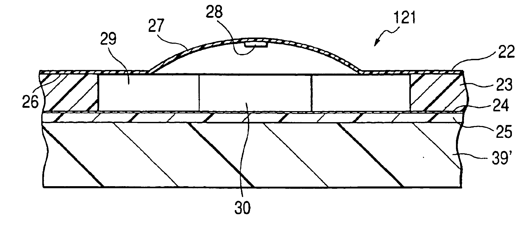
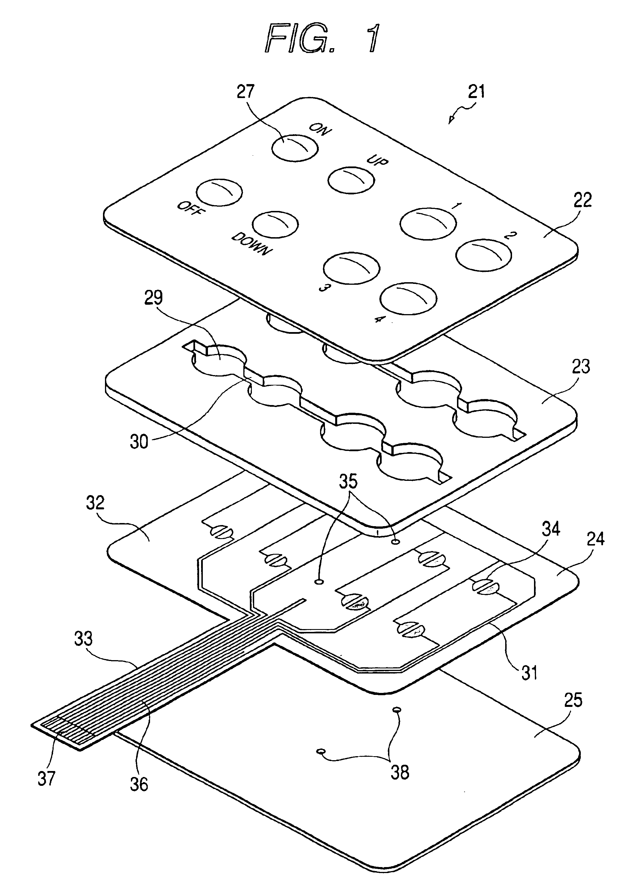
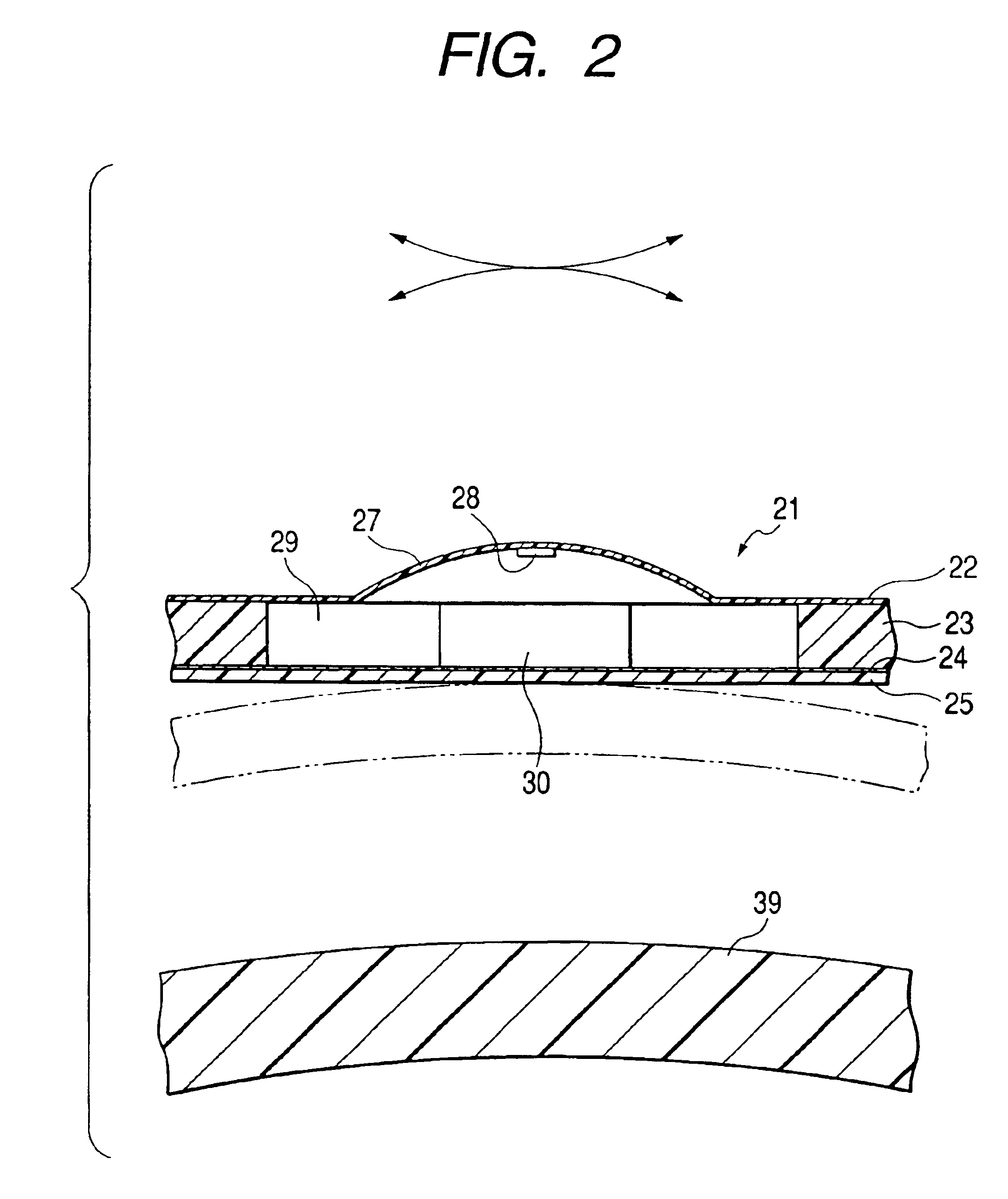
Next, the poly-dome switch of the second embodiment according to the present invention will be described below with reference to FIG. 5 to FIG. 8. FIG. 5 is an exploded perspective view of the second preferred embodiment of a variation-meeting dome switch of the invention. FIG. 6 is a cross-sectional view explanatory of the flexibility. FIG. 7 is a cross-sectional view showing a condition before the switch is operated. FIG. 8 is a cross-sectional view showing a condition when the switch is operated.

In FIG. 5, the poly-dome switch 121 comprises a front sheet 22, a spacer sheet 23, an FPC 24, and an adhesive sheet 25. In the poly-dome switch 121 of this embodiment, a molded, transparent member is used as the front sheet 22. A design portion 26 is provided on the inner face of the front sheet 22, and the poly-dome switch 121 can reflect the design change and model change of a machine and motor or a like on which the poly-dome switch 121 is attached by replacing only the front sheet 22....

seventh embodiment

A membrane switch of the seventh embodiment according to the present invention will be described with reference FIG. 32 to FIG. 34 Incidentally, in the membrane switch 321, components as same as the components described in the above embodiments are appended same reference numerals, and the detailed explanations regarding to the components are omitted.

In FIGS. 32 and 33, the membrane switch 321 comprises a front sheet 322, a spacer sheet 23, an first FPC 24, a spacer sheet 23′, a second FPC 324, and an adhesive sheet 25. Incidentally, the spacer sheet 23 is identical with the spacer sheet 23′.

first embodiment

The front sheet 322 is transparent, and has flexibility, and a plurality of projected portions 327. The front sheet 322 is identical with the front sheet 22 of the dome switch 21 except that the electrode 28 is not provided at an apex of in inner face of the front sheet 22. The FPC 324, having a flexibility, has a plurality of elastic members 323 and a plurality of electrodes 328. The elastic members 323 disposed at a position corresponding to the projected portions 327 are provided on a observe face of the FPC 324. The elastic member 323 is made of such as elastomer and rubber. The electrodes 328 disposed at a position corresponding to the projected portions 327 are provided on a reverse face of the FPC 324.

Next, the membrane switch 321 is assembled in the following manner. First, the front sheet 322 is adhesively bonded to the obverse face of the spacer sheet 23, and the FPC 324 is adhesively bonded to the reverse face of the spacer sheet 23. Next, the FPC 324 is adhesively bonde...


PUM


Abstract

In a flexible switch, a circuit member having an electrode is provided on a adhesive sheet. A spacer sheet, having a through hole situated so as to correspond to the electrode on the circuit member, is provided on the circuit member. A front sheet, having a projected portion, is provided on the spacer sheet, in which a contact portion provided on an inner face of the projected portion is brought into contact with the electrode through the through hole in the circuit member when the projected portion is depressed. At least one of the adhesive sheet, the circuit member, the spacer sheet, and the front sheet has flexibility.

Description

BACKGROUND OF THE INVENTIONThis invention relates to a flexible switch comprising a front sheet, having dome-like projected portions, a spacer sheet, a circuit member, and an adhesive sheet and a method for the flexible switch.FIGS. 35 and 36 show the first embodiment of a related switch. In FIGS. 35 and 36, this related switch comprises a board 411, having a switching circuit (not shown) formed on a face thereof, an integral-type rubber switch unit 415, an integral-type key top unit 420, and a casing 413. The board 411, the integral-type rubber switch unit 415 and the integral-type key top unit 420 are fixedly secured by screws 412 to the casing 413 in a generally laminated manner.With respect to the integral-type rubber switch unit 415, reference numeral 416 denotes rubber switch portions, reference numeral 416a denotes a flaring portion, and reference numeral 416b denotes an electrode. With respect to the integral-type key top unit 420, reference numeral 421 denotes key tops, ref...

Claims


Application Information

Patent Timeline
IPC IPC(8): H01H13/70H01H13/702H01H13/703
CPCH01H13/702H01H2231/026H01H2207/004H01H2209/004H01H2209/012H01H2209/014H01H2209/03H01H2209/052H01H2209/074H01H2213/002H01H2213/01H01H2215/006H01H2215/008H01H2223/014H01H2223/022H01H2229/022H01H2231/022H01H13/703
Inventor SERIZAWA, YASUYOSHIKUBOTA, MINORUNISHITANI, KEIZOKAWAGUCHI, KENICHIRO
Owner YAZAKI CORP
Why Eureka
Try Eureka