Ideal invisible antenna housing working at dual frequency bands

A radome and dual-band technology, applied in the field of radome, can solve the problem that the refractive index is not 1, and achieve the effect of high transmission coefficient, thin thickness and light weight

Pending Publication Date: 2022-03-25
ZHEJIANG UNIV
View PDF0 Cites 0 Cited by
  • Summary
  • Abstract
  • Description
  • Claims
  • Application Information

AI Technical Summary

Problems solved by technology

Although these traditional methods can match the impedance of the radome (with good transmission characteristics), they cannot avoid the phase distortion caused by the introduction of the radome itself, that is, when the electromagnetic wave enters the radome from different angles, the phase of the transmitted wave is distorted. The iso-phase planes of the transmitted waves are no longer equal to the iso-phase planes of the incident waves
The root cause of this situation is that the radome, despite being impedance matched, does not have a refractive index of 1

Method used


Image

  • Ideal invisible antenna housing working at dual frequency bands
  • Ideal invisible antenna housing working at dual frequency bands
  • Ideal invisible antenna housing working at dual frequency bands

Examples


Embodiment Construction

[0036] The present invention will be described in further detail below in conjunction with the accompanying drawings and specific embodiments.

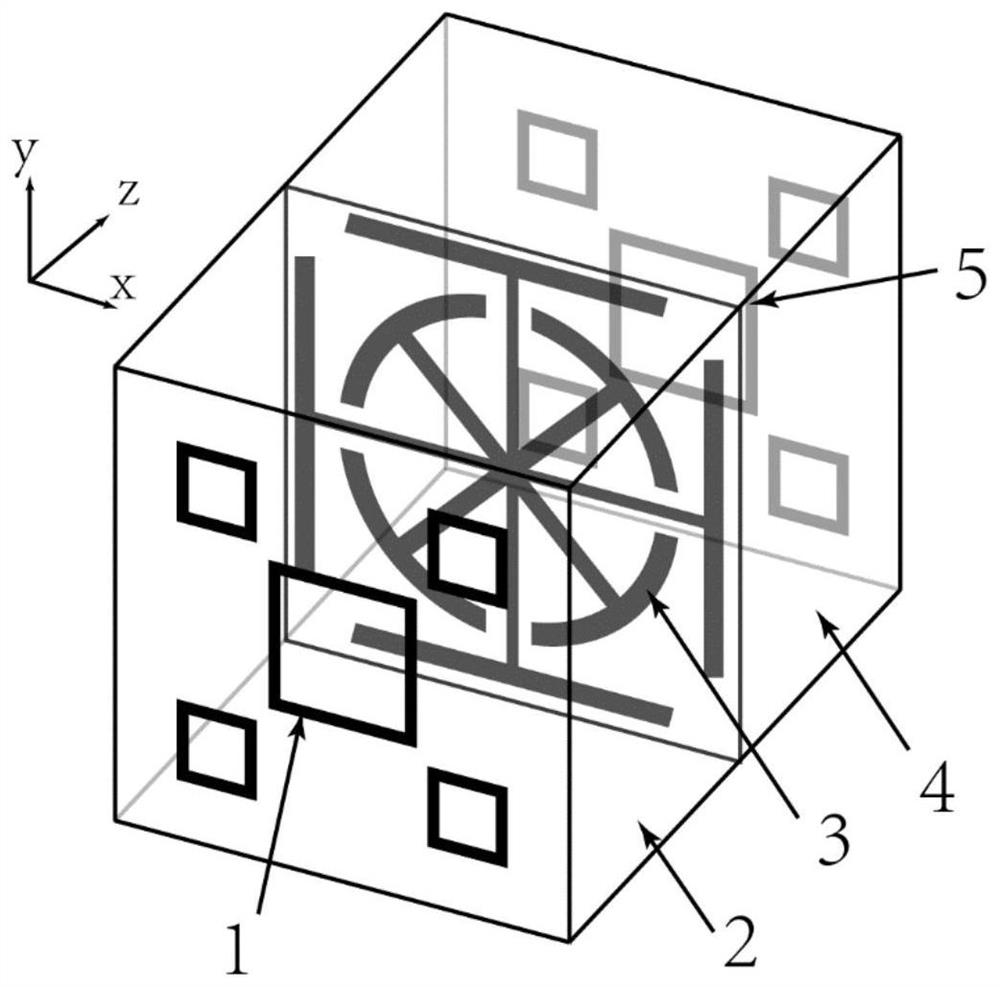
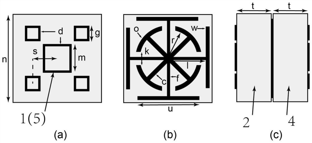
[0037] Such as figure 1 As shown, the radome is mainly composed of a plurality of square sub-wavelength resonant units closely arranged periodically on the same plane, and each sub-wavelength resonant unit is mainly composed of the first metal circuit layer 1, the first dielectric layer 2, and the The second metal circuit layer 3, the second dielectric layer 4 and the third metal circuit layer 5 are composed.

[0038] The first metal circuit layer 1 and the third metal circuit layer 5 are symmetrically arranged on the plane where the second metal circuit layer 3 is located. The end faces of layers 2 and 4 are concentric, and the other four identical rectangular metal frames are symmetrically distributed on the four corners of the end faces of the dielectric layers 2 and 4, and the centers of the four identical rectangular metal frame...


PUM


Abstract

The invention discloses an ideal invisible antenna housing working at double frequency bands. The radome is mainly formed by periodically arranging sub-wavelength resonance units, and each sub-wavelength resonance unit is mainly composed of a first metal circuit layer, a first dielectric layer, a second metal circuit layer, a second dielectric layer and a third metal circuit layer which are sequentially stacked. The first metal circuit layer and the third metal circuit layer are symmetrically arranged relative to the plane where the second metal circuit layer is located, and each comprises five rectangular metal frames; the first dielectric layer and the second dielectric layer are symmetrically arranged about the plane where the second metal circuit layer is located. The device is thin in thickness, light in weight and simple in structure, the electromagnetic property of the device is equivalent to that of air, and the device has an excellent transmission effect on incident plane waves at all angles. The method can be widely applied to the fields of electromagnetic transparent windows, radomes and the like.

Description

technical field [0001] The invention provides a radome, in particular to an ideal invisible radome which is formed by periodic arrangement of sub-wavelength resonant units and works in dual frequency bands. Background technique [0002] The radome is also called the electromagnetic window. While ensuring the good transmission of specific frequency signals, it also protects the electronic equipment system inside the hood from extreme weather (such as rain, snow, sand, birds, beasts, high temperature, etc.) etc.) effects. Common radome includes vehicle radar radome, nose radar radome, communication base station radome, etc. Because the assembly of radome can prevent the more expensive electronic communication equipment from being directly attacked by various extreme weather, effectively guaranteeing the life and working stability of the equipment, so the radome is widely used in various signal transmission and reception fields such as antennas and radars. [0003] Electronic...

Claims


Application Information

Patent Timeline
IPC IPC(8): H01Q1/42
CPCH01Q1/422
Inventor 黄正杰王婕胡晓俊余慧龙任建华冉立新叶德信
Owner ZHEJIANG UNIV
Why Eureka
Try Eureka