

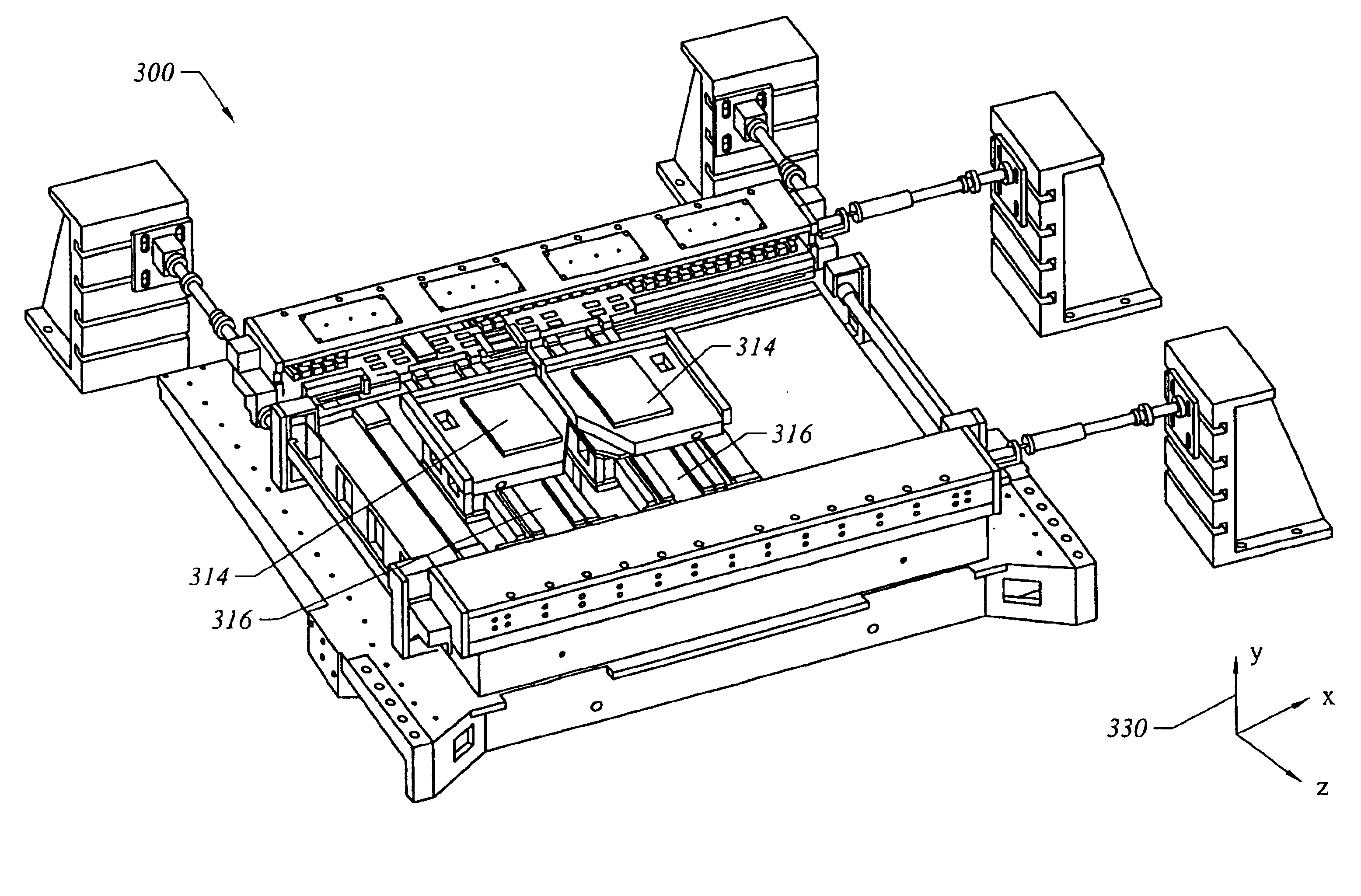
Actuator to correct for off center-of-gravity line of force
a technology of center-of-gravity force and actuator, which is applied in the direction of motor/generator/converter stopper, dynamo-electric converter control, instruments, etc., can solve the problems of image projection by the photolithography machine, function improperly, and product formation using the precision instrumen
- Summary
- Abstract
- Description
- Claims
- Application Information
AI Technical Summary
Benefits of technology
Problems solved by technology
Method used
Image

Examples
Embodiment Construction
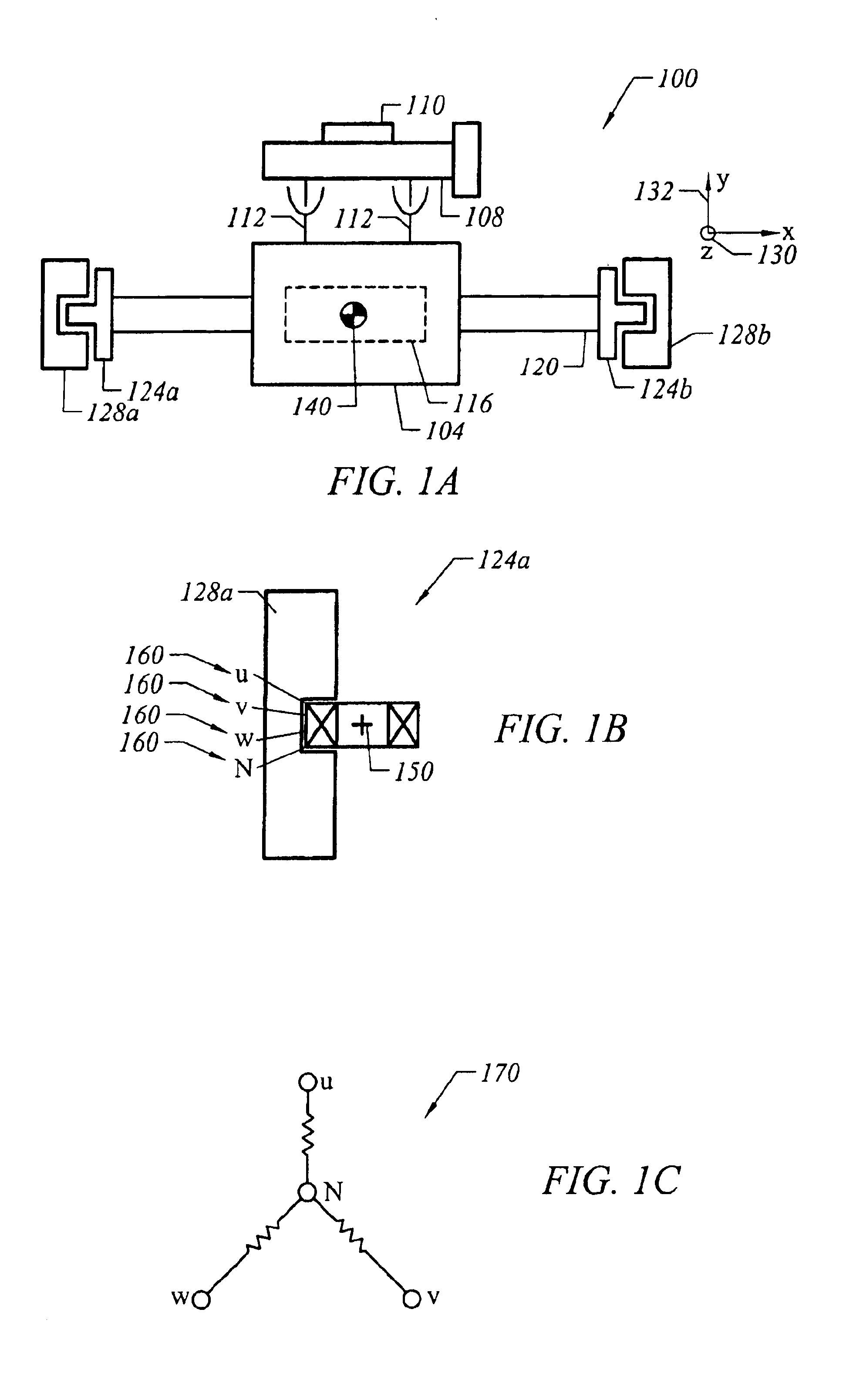
When a stage such as a lithography stage is not driven through approximately the center of gravity of the stage, pitching moments may be generated which may adversely affect the performance of the stage as well as the overall stage device. Therefore, many stage devices are designed to align an actuator push point, or center of force, with the center-of-gravity of the stage that is being driven by the actuator to be on the same plane in as far as possible. Often, since errors in alignment may result in between approximately a five millimeter (mm) and approximately a ten mm mismatch between the push point and the center of gravity, methods to compensate for the errors in alignment are introduced. While such methods typically involve adding adjustable masses, as for example to the stage, to move the effective center-of-gravity of the stage and may be effective, the masses are often heavy, and may cause an increased motor force and more complicated dynamics.
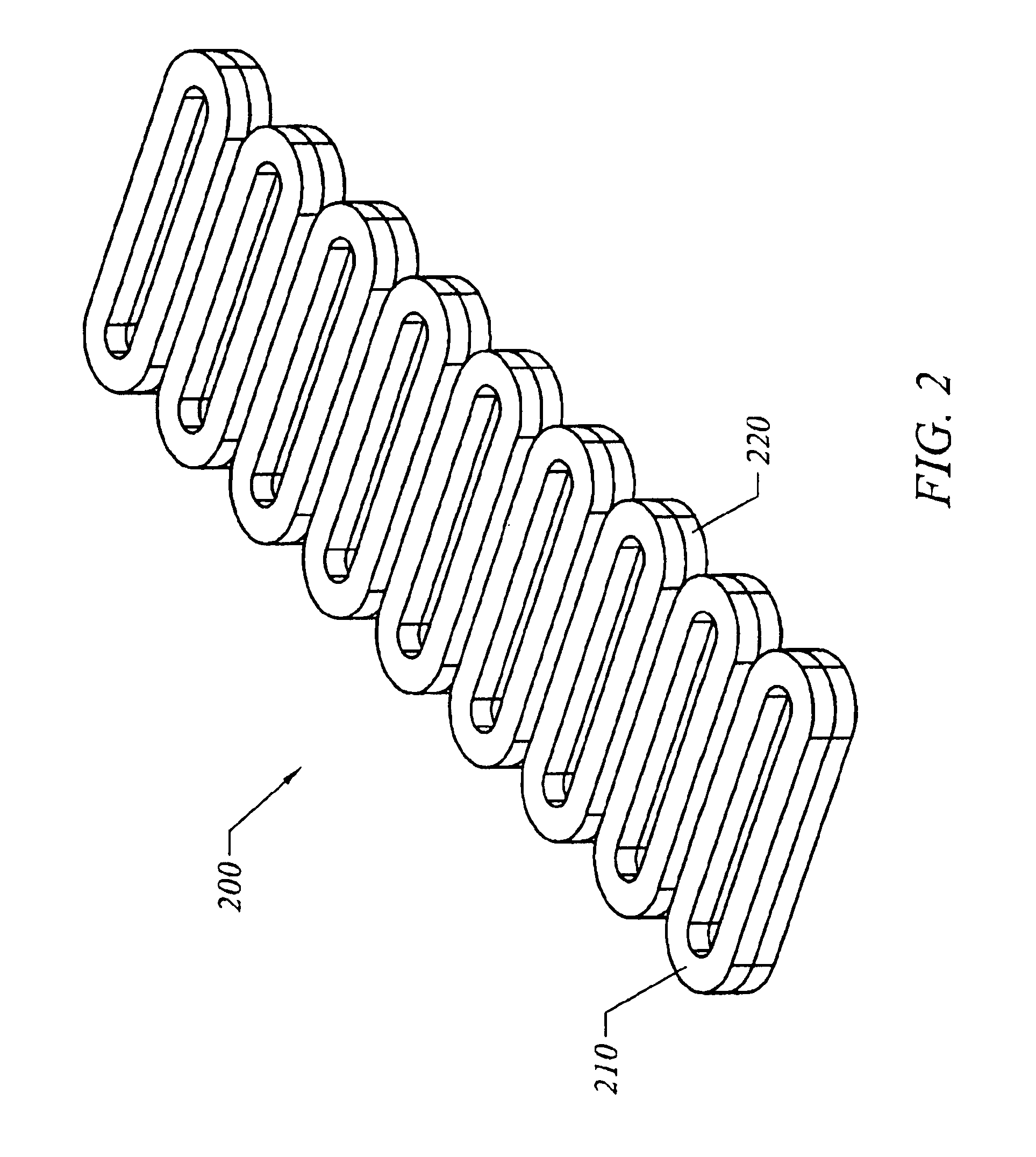
A force actuator such as a mo...
PUM
| Property | Measurement | Unit |
|---|---|---|
| velocity | aaaaa | aaaaa |
| wavelength | aaaaa | aaaaa |
| voltage | aaaaa | aaaaa |
Abstract
Description
Claims
Application Information