Fabrication method and apparatus for antenna structures in wireless communications devices

a technology of wireless communication device and antenna structure, which is applied in the direction of antennas, antenna details, basic electric elements, etc., can solve the problems of large space occupied by printed circuit antennas, small packaging of state-of-the-art communications devices, and insufficient space for quarter-and-half-wave length antenna elements. achieve the effect of reducing the space occupied by antennas, reducing the cost of printed circuit antennas, and reducing the cost of antennas

Inactive Publication Date: 2005-01-11
SKYCROSS INC
View PDF47 Cites 47 Cited by
  • Summary
  • Abstract
  • Description
  • Claims
  • Application Information

AI Technical Summary

Benefits of technology

A meanderline antenna such as described above, offers desirable attributes within a smaller physical volume than prior art antennas, while exhibiting comparable or enhanced performance over conventional antennas. To gain additional b

Problems solved by technology

Smaller packaging of state-of-the-art communications devices does not provide sufficient space for the conventional quarter and half wave length antenna elements.
Given the costs associated with the indivi

Method used


Image

  • Fabrication method and apparatus for antenna structures in wireless communications devices
  • Fabrication method and apparatus for antenna structures in wireless communications devices
  • Fabrication method and apparatus for antenna structures in wireless communications devices

Examples


Embodiment Construction

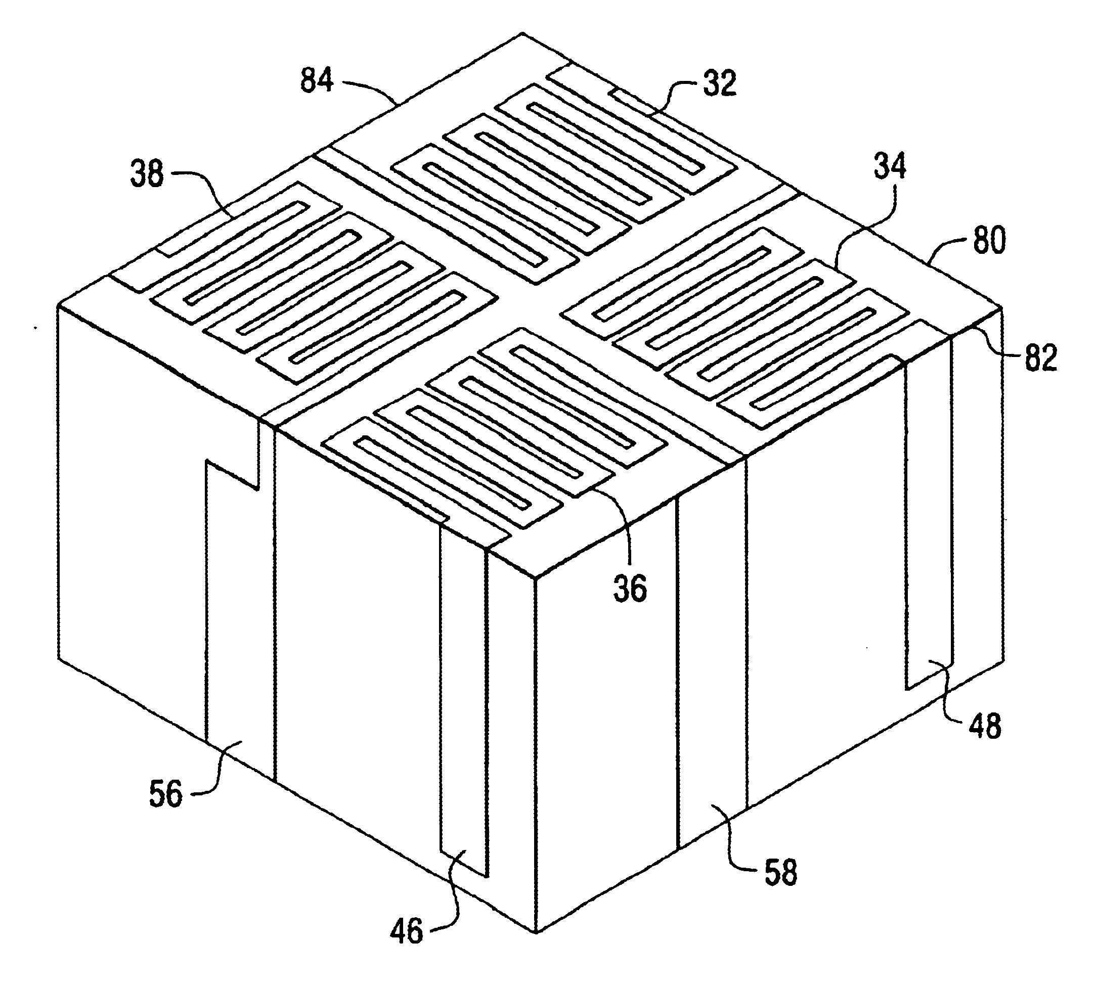
Before describing in detail the particular meanderline-loaded antenna constructed according to the teachings of the present invention, it should be observed that the present invention resides primarily in a novel and non-obvious combination of method steps and elements related to antennas structures and antenna technology in general. Accordingly, the hardware components and method steps described herein have been represented by conventional elements in the drawings and in the specification description, showing only those specific details that are pertinent to the present invention, so as not to obscure the disclosure with details that will be readily apparent to those skilled in the art having the benefit of the description herein.

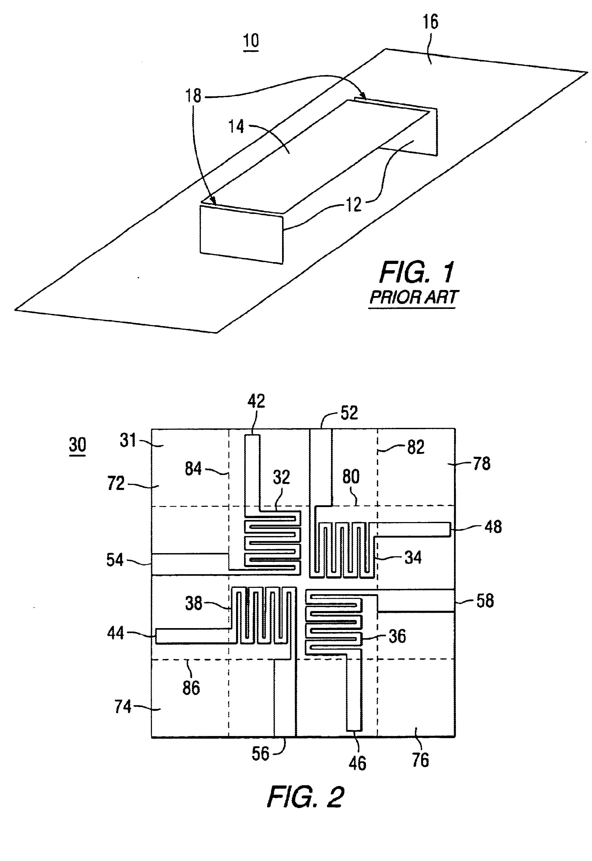
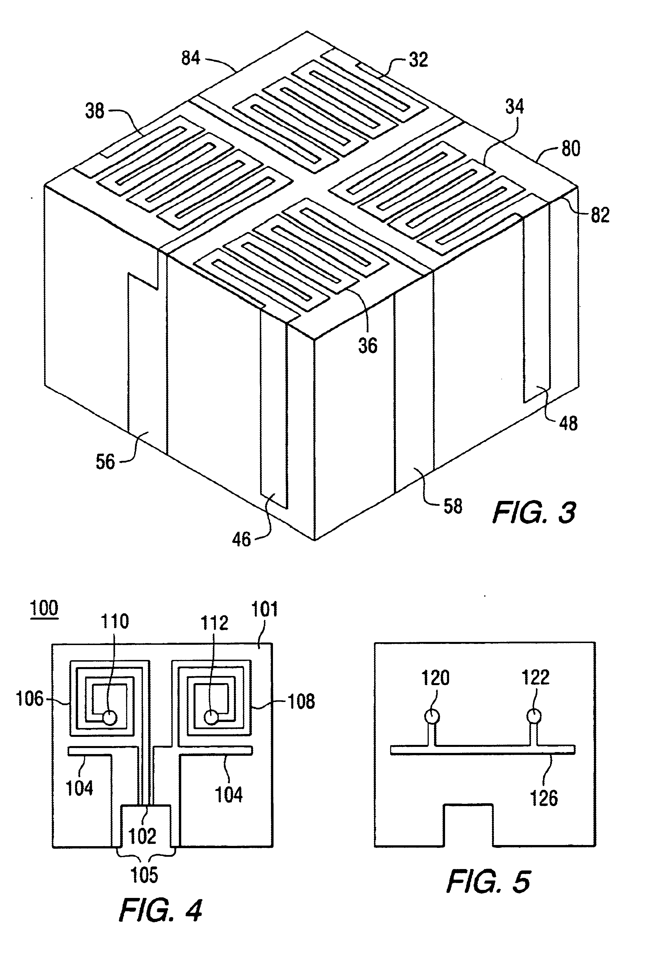
FIG. 1 depicts a perspective view of a prior art meanderline-loaded antenna 10 (also referred to as a variable impedance transmission line antenna) to which the teachings of the present invention can be advantageously applied. The meanderline-loaded antenn...


PUM


Abstract

There is disclosed a meanderline loaded antenna formed by applying a conductive ink or other conductive material to a flexible substrate. The substrate is then shaped by removing regions and folding other regions along perforated or scored lines to fit the antenna within the available space of a wireless device. In lieu of folding regions of a planar substrate to form a three-dimensional structure, the substrate can be vacuum formed over a mandrel after the antenna elements have been formed thereon. The antenna can also be formed by printing on existing enclosure surfaces of a wireless device or on the surfaces of components within the device. Thus the advantages offered by a meanderline antenna where the effective electrical length is greater than the actual physical length are achieved in conjunction with a space-saving physical structure for the antenna.

Description

FIELD OF THE INVENTIONThis invention relates generally to antennas comprising slow wave structures, and especially to such antennas formed using conductive ink processes.BACKGROUND OF THE INVENTIONIt is generally known that antenna performance is dependent upon the size, shape and material composition of the constituent antenna elements, as well as the relationship between certain antenna physical parameters (e.g., length for a linear antenna and diameter for a loop antenna) and the wavelength of the signal received or transmitted by the antenna. These relationships determine several antenna operational parameters, including input impedance, gain, directivity and the radiation pattern. Generally for an operable antenna, the minimum physical antenna dimension (or the electrically effective minimum distance) must be on the order of a quarter wavelength (or a multiple thereof) of the operating frequency, which thereby advantageously limits the energy dissipated in resistive losses and ...

Claims


Application Information

Patent Timeline
IPC IPC(8): H01Q1/38H01Q1/36
CPCH01Q1/38H01Q1/36
Inventor HENDLER, JASON M.ASBURY, FLOYD A.CAIMI, FRANK M.THURSBY, MICHAEL H.GREER, KERRY L.
Owner SKYCROSS INC
Why Eureka
Try Eureka