Acoustic logging apparatus and method

a technology of acoustic wells and logging apparatus, which is applied in the field of acoustic wells, can solve the problem that the determination of slowness in this matter is not suitable for error estimation

Inactive Publication Date: 2005-01-11
HALLIBURTON ENERGY SERVICES INC
View PDF41 Cites 34 Cited by
  • Summary
  • Abstract
  • Description
  • Claims
  • Application Information

AI Technical Summary

Benefits of technology

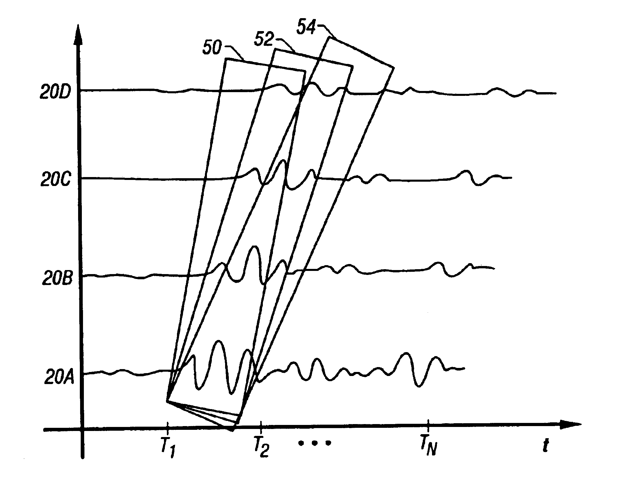
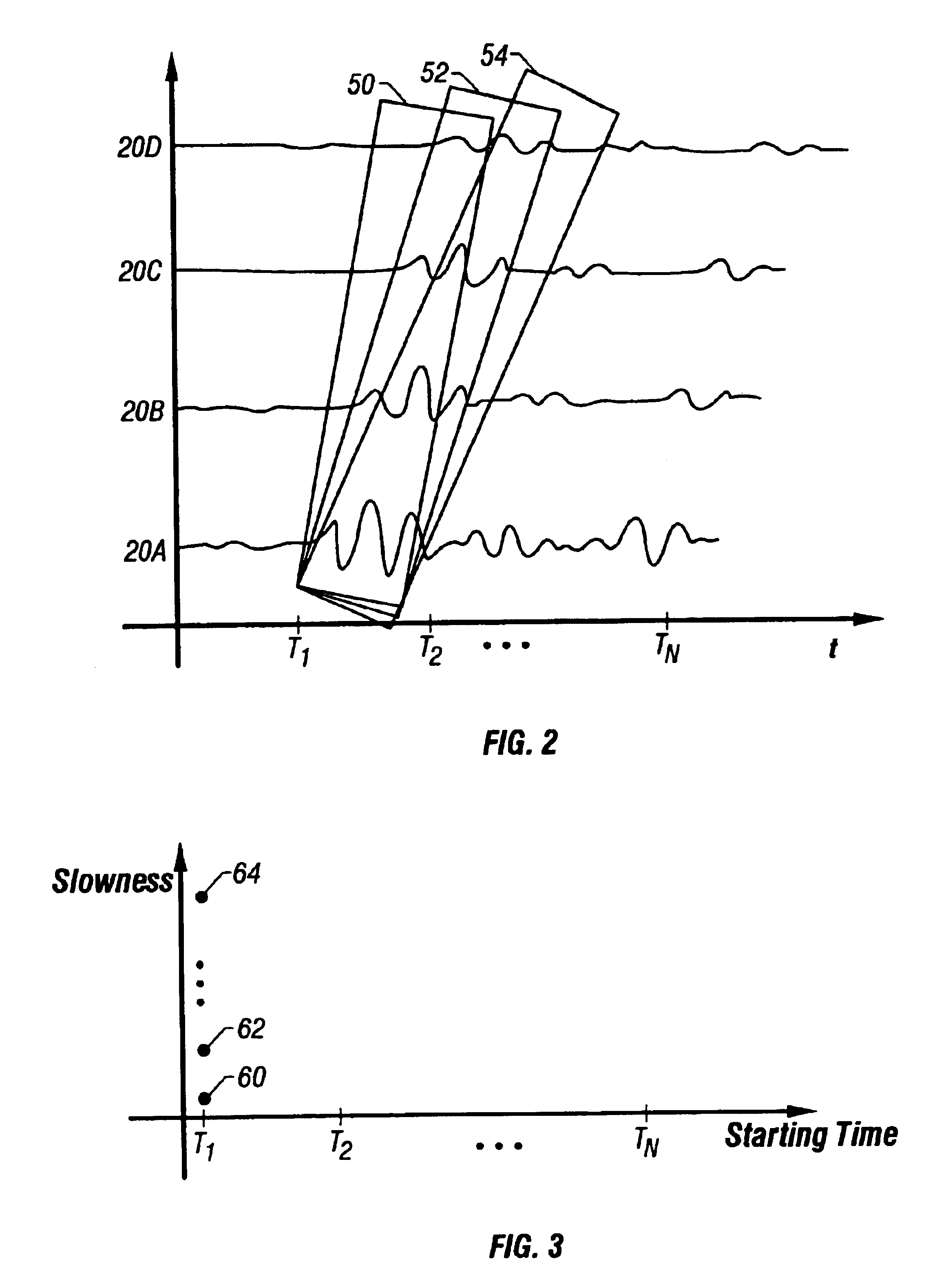
A first embodiment for comparing estimated source signals involves determining a variance of each of the estimated source signals against an average estimated source signal. This embodiment involves calculating an average of the estimated source signals, and then calculating a variance of the individual source signals against the average source signal. The variance values, which are the objective function in this case, may be plotted in such a way that the plot that looks similar to the time slowness plot used in semblance / coherence processing, but has two distinct advantages. First, the variance values have sharper transitions to the inflection points (minima in the preferred embodiments) than the semblance / coherence of the prior art, and therefore a more exact value of the slowness may be determined. Second, both of tie variance values themselves, and the curvature of the objective function at the minima, are indicative of the accuracy of the slowness determination. That is, a particular plot of information may reveal a slowness value, and also indicates the relative accuracy of the slowness determination.
The second embodiment for determining the slowness of the formation of the preferred embodiments involves comparing each estimated source signal with its immediate neighbor to determine a difference, and then summing the square of the differences to obtain a value of the objective function. The values of the objective function may likewise be plotted in a time slowness plot to reveal a graph similar to a semblance / coherence plot familiar to one of ordinary skill in the art. The advantage of this second embodiment is that the plotted objective function has slower transitions from maxima to minima such that the determination of the minima points (determining the slowness values) may be accomplished with less computational overhead. In other words, determining inflection points in objective functions created by the differential comparison is at least as computationally fast as traditional semblance / coherence processing. Also, the values of the objective function at the minima and / or the curvature of the objective function at the minima is indicative of the error in the slowness determination.

Problems solved by technology

While semblance / coherence may create visually pleasing results, determining slowness in this matter is not suitable for error estimation.

Method used


Image

  • Acoustic logging apparatus and method
  • Acoustic logging apparatus and method
  • Acoustic logging apparatus and method

Examples


first embodiment

A first embodiment for comparing estimated source signals involves determining a variance of each of the estimated source signals against an average estimated source signal. This embodiment involves calculating an average of the estimated source signals, and then calculating a variance of the individual source signals against the average source signal. The variance values, which are the objective function in this case, may be plotted in such a way that the plot that looks similar to the time slowness plot used in semblance / coherence processing, but has two distinct advantages. First, the variance values have sharper transitions to the inflection points (minima in the preferred embodiments) than the semblance / coherence of the prior art, and therefore a more exact value of the slowness may be determined. Second, both of tie variance values themselves, and the curvature of the objective function at the minima, are indicative of the accuracy of the slowness determination. That is, a par...

second embodiment

The second embodiment for determining the slowness of the formation of the preferred embodiments involves comparing each estimated source signal with its immediate neighbor to determine a difference, and then summing the square of the differences to obtain a value of the objective function. The values of the objective function may likewise be plotted in a time slowness plot to reveal a graph similar to a semblance / coherence plot familiar to one of ordinary skill in the art. The advantage of this second embodiment is that the plotted objective function has slower transitions from maxima to minima such that the determination of the minima points (determining the slowness values) may be accomplished with less computational overhead. In other words, determining inflection points in objective functions created by the differential comparison is at least as computationally fast as traditional semblance / coherence processing. Also, the values of the objective function at the minima and / or th...


PUM


Abstract

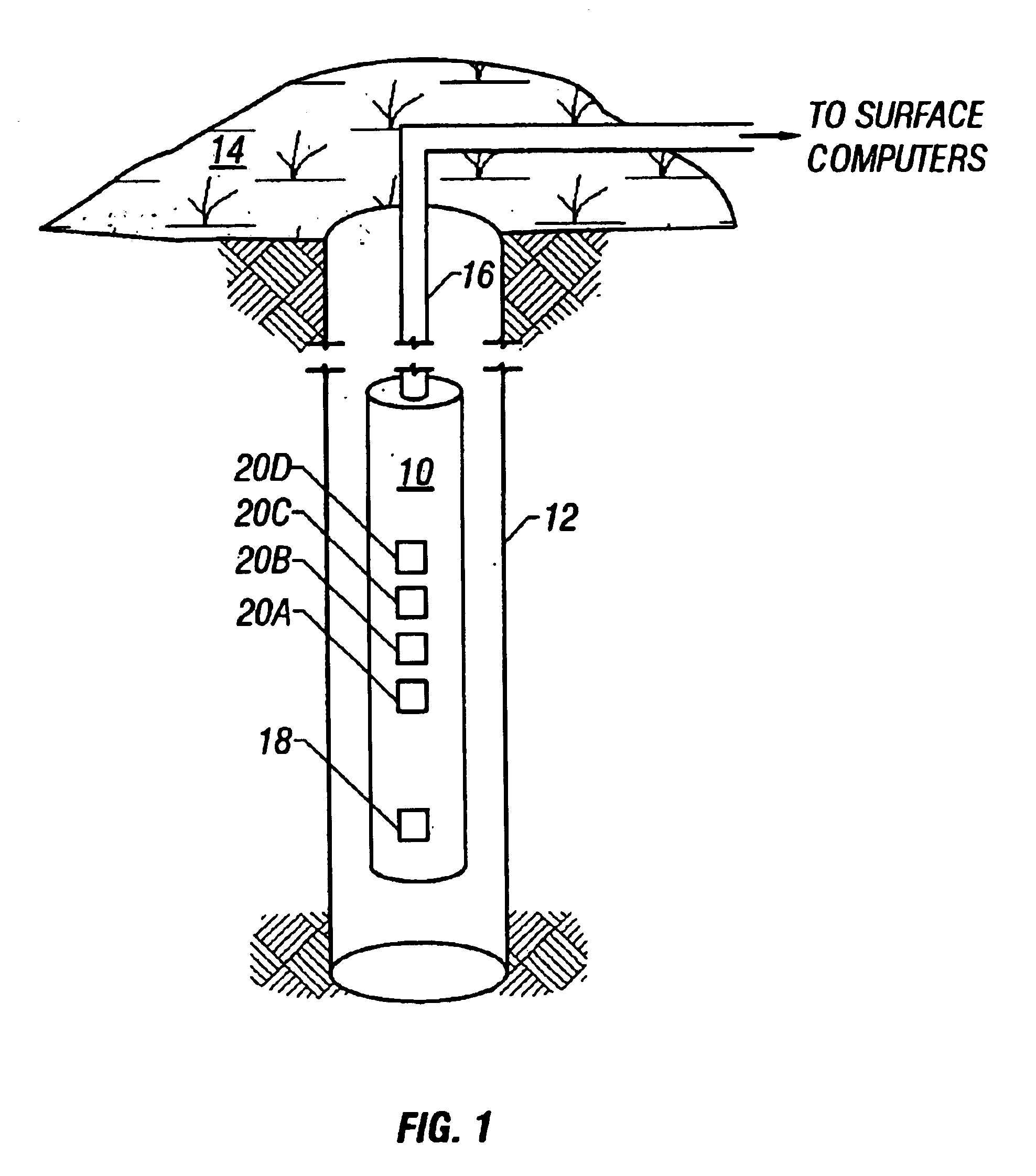
The specification discloses a system and related method for determining characteristics of earth formations traversed by a borehole. An acoustic transmitter mounted on a tool, whether that tool is a wireline tool or a logging-while-drilling tool, imparts acoustic energy into the formation, and a plurality of receivers spaced apart from the transmitter and from each other receive acoustic energy responsive to the transmitter firing. Portions, or all, of each received signal are used to estimate source signals using an assumed transfer function. Each of those estimated source signals are then compared in some way to determine an objective function. This process is repeated for multiple assumed transfer functions, and at multiple starting times within the received signals. By searching for minimas of a plot of the objective function, characteristics of the earth formation may be determined.

Description

STATEMENT REGARDING FEDERALLY SPONSORED RESEARCH OR DEVELOPMENTNot applicable.BACKGROUND OF THE INVENTION1. Field of the InventionThe present invention relates generally to acoustic well logging. More particularly, the present invention relates to determining the velocity (slowness) of acoustic waves in an earth formation.2. Description of the Related ArtIn the art of acoustic logging, the formation properties of interest are one or more of the compressional wave velocity, the shear wave velocity and the Stonley wave velocity. These acoustic velocities are indicative of the formation's ability to hold and produce hydrocarbons. Operation of a typical acoustic formation tool may involve placing the tool in the well bore and firing one or more acoustic transmitters periodically, thus launching acoustic energy into the formation. The acoustic energy thus produced propagates along the formation wall in one or more propagation modes, e.g. compressional or shear wave modes. Receivers on th...

Claims


Application Information

Patent Timeline
Patent Type & Authority Patents(United States)
IPC IPC(8): G01V1/50G01V1/48G01V1/40
CPCG01V1/50G01V1/48
Inventor BLANCH, JOAKIM O.VARSAMIS, GEORGIOS L.
Owner HALLIBURTON ENERGY SERVICES INC
Why Eureka
Try Eureka