Information recording method and optical disc apparatus

a technology of information recording and optical disc, applied in the direction of digital signal error detection/correction, instruments, recording signal processing, etc., can solve the problem of unsatisfactory heat generation, and achieve the effect of suppressing edge shift and good jitter

Inactive Publication Date: 2005-01-11
HITACHI CONSUMER ELECTRONICS CORP
View PDF11 Cites 44 Cited by
  • Summary
  • Abstract
  • Description
  • Claims
  • Application Information

AI Technical Summary

Benefits of technology

According to the present invention, it is possible to provide an optical disc apparatus which suppresses an edge shift caused by the shape change of the reco

Problems solved by technology

Furthermore, the high speed rotation of the motor may cause he

Method used


Image

  • Information recording method and optical disc apparatus
  • Information recording method and optical disc apparatus
  • Information recording method and optical disc apparatus

Examples


embodiment 1

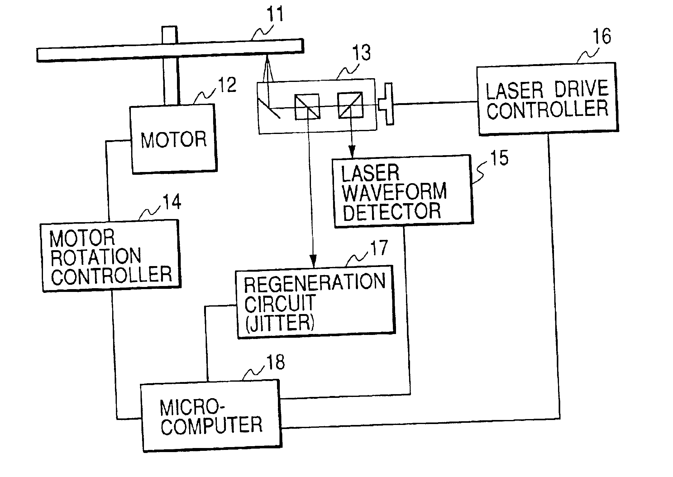
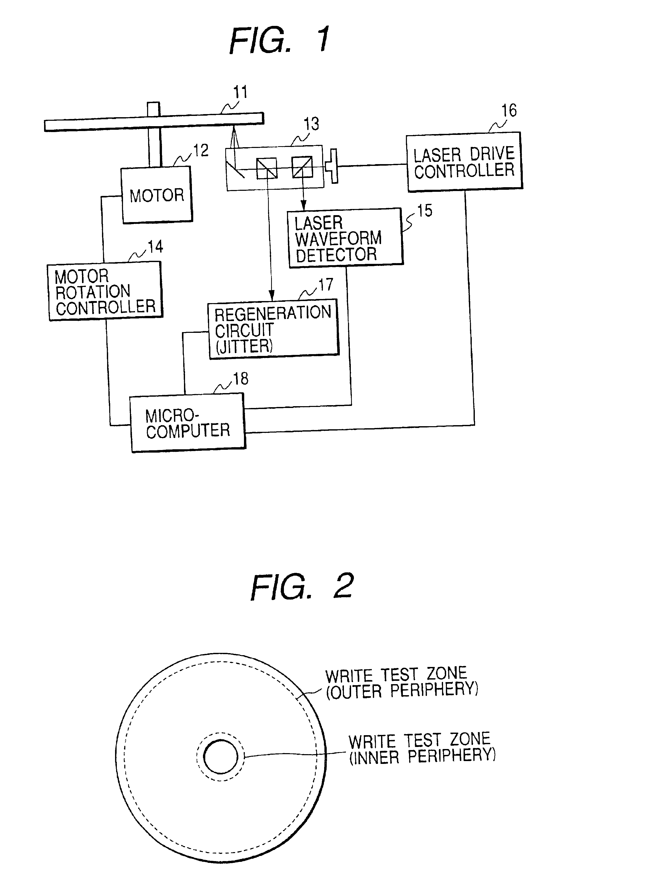
An optical disc having a diameter of 8 cm was prepared. This optical disc has good jitter at a linear velocity of 8.2 m / s all over the recordable area thereof In this embodiment, recording / reproducing of the optical disc was performed by use of an optical disc apparatus shown in FIG. 1. As a method of controlling a motor dining the recording / reproducing, a ZCAV scheme was adopted, in which a linear velocity of the disc, a clock frequency T and a window width Tw defined by an inverse number of the clock frequency T are changed for each zone where the recording / reproducing is performed.

FIG. 1 is a schematic view showing an outline of an optical disc apparatus of the present invention. For simplifying the description, FIG. 1 shows only the minimum constitution of the device necessary for descriptions of the present invention. This optical disc apparatus comprises a motor rotation controller 14 for allowing a motor 12 to rotate, an optical head 13 for radiating a laser beam from a semic...

embodiment 2

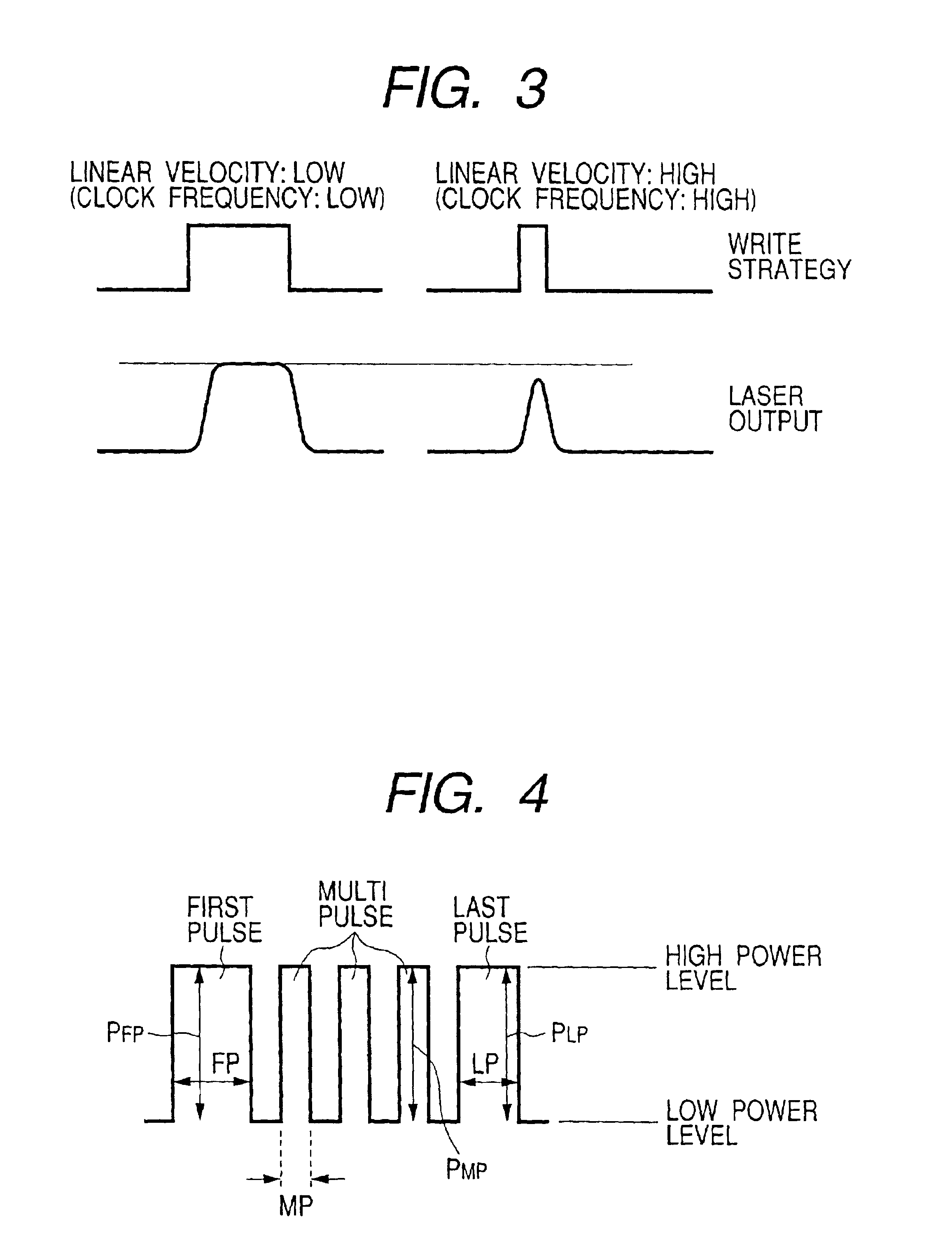
An optical disc having a diameter of 12 cm was prepared. To perform the CAV or ZCAV recording in the optical disc having the diameter of 12 cm, the linear velocity is 21 m / s on the outer periphery of the disc when the linear velocity is 8.2 m / s on the inner periphery thereof. Also the clock frequency and the window width change accompanied with the change of the linear velocity. For example, when the window width Tw is 17.1 ns at the linear velocity of 8.2 m / s, the window width Tw is 8.6 ns at the linear velocity of 16.4 m / s, and 6.7 ns at the linear velocity of 21 m / s. As described above, as the linear velocity becomes higher, the window width becomes shorter. Accompanied with this, light emission time becomes shorter, so that influences of rise-up time of a laser become significant.

FIG. 8 shows a light emission pulse detected by the laser waveform detector 15 of FIG. 1, when the linear velocity (window width) is changed. In the device used in this embodiment, when the linear veloc...


PUM


Abstract

Good jitter is retained and recorded even when a linear velocity is variable. A recording parameter suitable for each of the linear velocities is obtained by performing test writings for an outer periphery zone of a disc at different linear velocities, and based on a correlation between each of the linear velocities and a recording parameter suitable for each of the linear velocities, a recording parameter corresponding to a linear velocity on an area onto which information is to be recorded is obtained.

Description

BACKGROUND OF THE INVENTION1. Field of the InventionThe present invention relates to an information recording method and an optical disc apparatus which record information onto an optical disc by use of light.2. Descriptions of the Related ArtsAn optical disc formatted in accordance with a ZCLV (Zoned Constant Linear Velocity) scheme is divided into a plurality of zones in its radius direction, and recording / reproducing of information in each zone is performed by a CAV (Constant Angular Velocity) scheme. A frequency of a recording / reproducing signal is constant, and the ZCLV scheme has a feature in that information can be recorded densely even in an external periphery of a disc like in an inner periphery thereof In a DVD-RAM disc, this ZCLV scheme is adopted, and a high density recording of 2.6 GB is achieved in a first generation, and a high density recording of 4.7 GB is achieved in a second generation. In this CAV scheme, since a linear velocity is made to be constant in both of ...

Claims


Application Information

Patent Timeline
IPC IPC(8): G11B7/125G11B7/00G11B7/006G11B7/0045G11B7/126
CPCG11B7/126G11B7/006
Inventor USHIYAMA, JUNKOMINEMURA, HIROYUKI
Owner HITACHI CONSUMER ELECTRONICS CORP
Why Eureka
Try Eureka