Optical disc reproducing apparatus

a technology of optical discs and reproducing apparatuses, applied in the direction of digital signal error detection/correction, instruments, recording signal processing, etc., can solve the problems of very time-consuming equalizer adjustment, so as to reduce short time, and the effect of reducing the number of times of measuremen

Inactive Publication Date: 2005-12-15
FUNAI ELECTRIC CO LTD
View PDF5 Cites 4 Cited by
  • Summary
  • Abstract
  • Description
  • Claims
  • Application Information

AI Technical Summary

Benefits of technology

[0029] As above described, according to the invention, the optical disc reproducing apparatus comprises the following system controller for searching for an optimal jitter value by simultaneously changing a cutoff frequency and a boost amount to thereby perform equalizer adjustment. This system controller comprises optical pickup setting unit for causing an optical pickup to seek a predetermined address on the optical disc so as to measure jitter and for setting the optical pickup in a pause state, measuring point setting unit for sequentially setting at least two points, which are located on a coordinate plane whose abscissas represent cutoff frequencies and whose ordinates represent boost amounts, as measuring points at each of which jitter is measured, for setting one of the measuring points as a reference search point, and for setting the other measuring point at a position displaced by a set value from the reference search point, first jitter bottom judging unit for judging, when a difference between a jitter value at one of the measuring points and a jitter value at the other measuring point is within a predetermined range, that both the measuring points are placed at a bottom of a jitter coordinate space, first adjustment value setting unit for setting, when it is judged that both the measuring points are placed at the bottom of the jitter coordinate space, a jitter value at the measuring point, which jitter value is better than that at the other measuring point, as an equalizer adjustment value, measuring point moving unit for moving, when a difference between a jitter value at one of the measuring points and a jitter value at the other measuring point is outside a predetermined range, the measuring point, the measured jitter value of which is larger than the measured jitter value of the other measuring point, between the measuring points by a set value, second jitter bottom judging unit for judging, when a difference between a jitter value at one of the measuring points and a jitter value at the other measuring point is within a predetermined range, that both the measuring points are placed at a bottom of a jitter coordinate space, and second adjustment value setting unit for setting, when it is judged that both the measuring points are placed at the bottom of the jitter coordinate space, a jitter value at the measuring point, the jitter at which is better than that at the other measuring point, as an equalizer adjustment value. Thus, the points located on the coordinate plane, whose abscissas represent cutoff frequencies and whose ordinates represent boost amounts, are determined as the measuring points. Consequently, when the measuring point is moved, the cutoff frequency and the boost amount simultaneously change. Thus, the number of times of measurement can be reduced by simultaneously changing the cutoff frequency and the boost amount. Optimal jitter can be searched for. Deviations of the cutoff frequency and the boost amount of a circuit can be absorbed. Optimal equalizer adjustment can be performed on each optical disc in a short time.
[0030] Also, according to the invention, the optical disc reproducing apparatus has the system controller that sets the positions of jitter measuring points determined by points located on the coordinate plane whose abscissas represent the cutoff frequencies and whose ordinates represent the boost amounts by simultaneously changing the cutoff frequency and the boost amount, and that searches for an optimal jitter value by moving the measuring points. Thus, the measuring points are determined by the points on the coordinate plane whose abscissas represent the cutoff frequencies and whose ordinates represent the boost amounts. Further, the movement of the measuring point results in the simultaneous change of the cutoff frequency and the boost amount. Thus, the number of times of measurement can be reduced. Optimal jitter can be searched for. Deviations of the cutoff frequency and the boost amount of a circuit can be absorbed. Optimal equalizer adjustment can be performed on each optical disc in a short time.

Problems solved by technology

Thus, the conventional apparatus has caused the problem that the equalizer adjustment is very time-consuming.
That is, the conventional optical disc reproducing apparatus has caused the problem that the equalizer adjustment is very time-consuming, because the equalizer adjustment is performed by varying the cutoff frequency and the boost amount separately from each other.
Thus, each of the conventional techniques has caused the problem that the equalizer adjustment is very time-consuming.

Method used


Image

  • Optical disc reproducing apparatus
  • Optical disc reproducing apparatus
  • Optical disc reproducing apparatus

Examples


Embodiment Construction

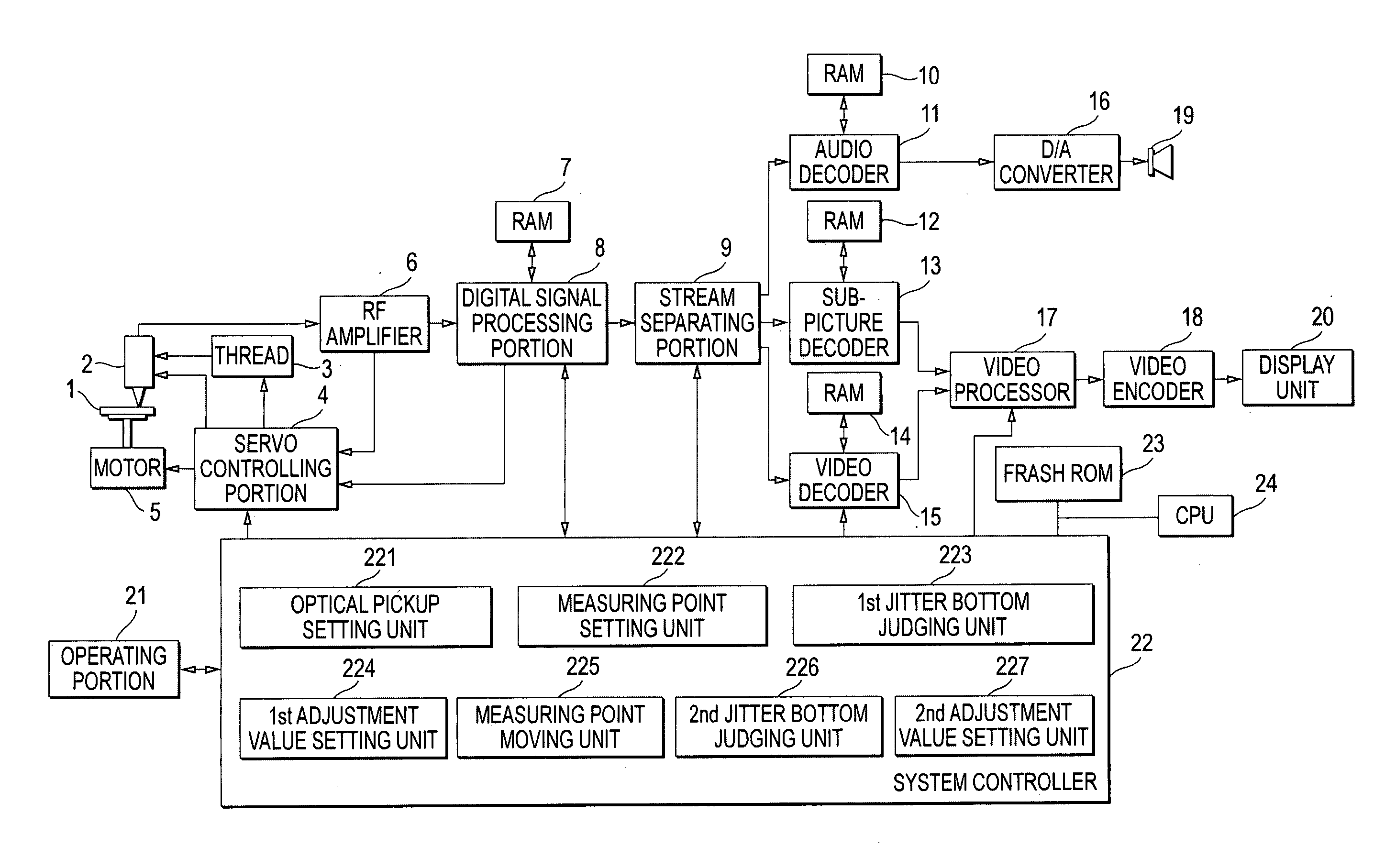
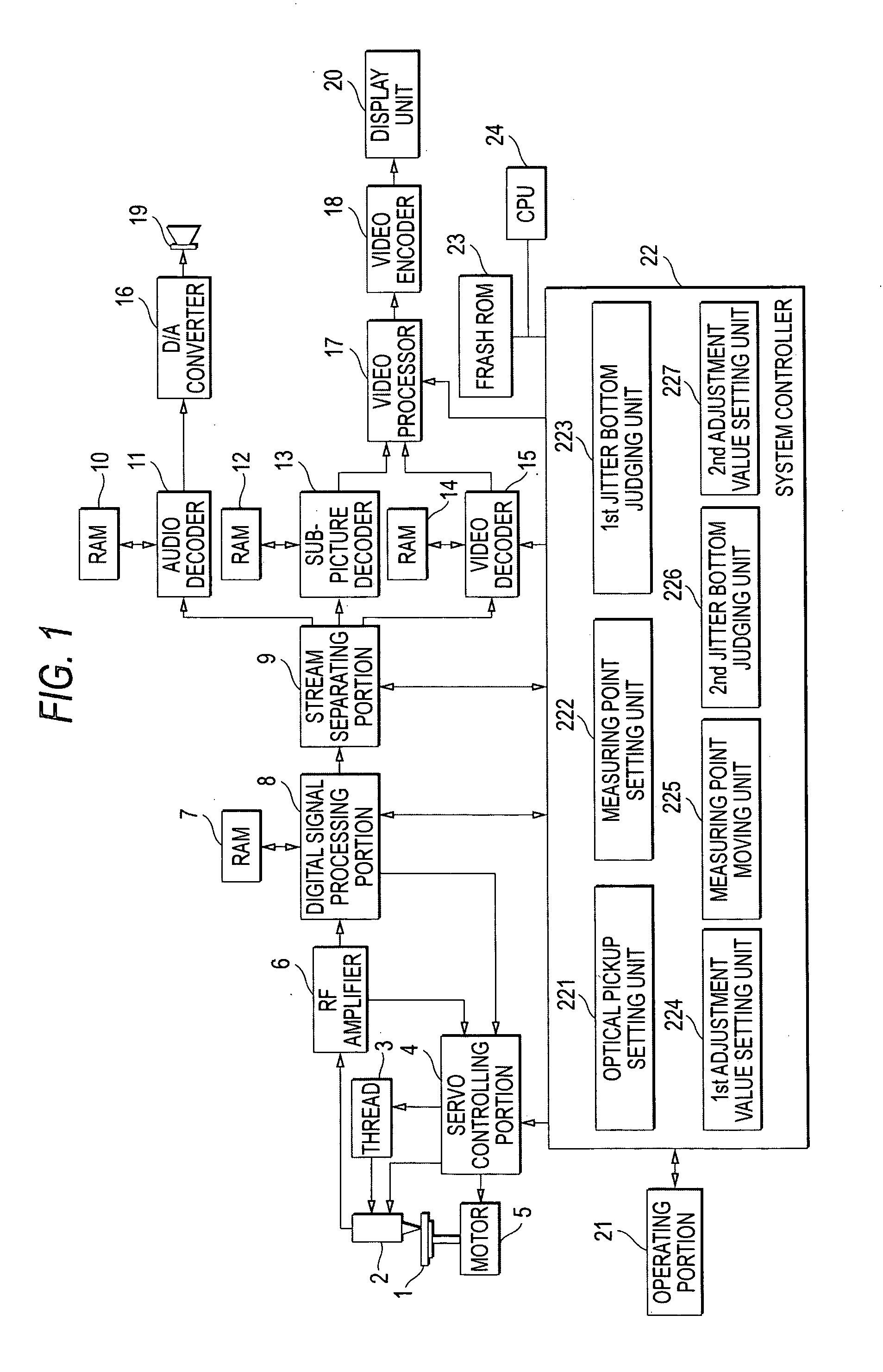
[0042] Hereinafter, an embodiment of the invention is described with reference to the accompanying drawings. FIG. 1 is a block view illustrating the configuration of an optical disc reproducing apparatus according to an embodiment of the invention. This optical disc reproducing apparatus has a spindle motor 5 for causing an optical disc 1 to rotate, an optical pickup 2 for outputting laser light, which is used for reproducing information recorded on the optical disc 1, and for receiving light reflected from the optical disc 1, a sled 3 for moving this optical pickup 2 in the direction of a radius of an optical disc 1, and a servo control portion 4 for driving the spindle motor 5 and the sled 3 in response to instructions issued by the system controller 22 and for moving a focus position of laser light vertically and horizontally with respect to a recording surface of the optical disc 1 by moving an objective lens (not shown) incorporated in the optical pickup 2.

[0043] This optical ...


PUM

PropertyMeasurementUnit
cutoff frequencyaaaaaaaaaa
cutoff frequenciesaaaaaaaaaa
frequencyaaaaaaaaaa

Abstract

An optical disc reproducing apparatus has a function of setting a cutoff frequency and a boost amount of a read out signal from an optical disc and performing equalizer adjustment, and includes a system controller for searching for an optimal jitter value by simultaneously changing a cutoff frequency and a boost amount to thereby set positions of jitter measuring points determined on a coordinate plane whose abscissas represent cutoff frequencies and whose ordinates represent boost amounts, and by moving the measuring points.

Description

BACKGROUND OF THE INVENTION [0001] 1. Field of the Invention [0002] The present invention relates to an optical disc reproducing apparatus for reproducing information recorded on an optical disc and, more particularly, to an optical disc reproducing apparatus having a function of performing equalizer adjustment therein. [0003] 2. Description of the Related Art [0004] As has hitherto been known, in an optical disc reproducing apparatus for reproducing information recorded on an optical disc, such as a CD (compact disk) or a DVD (digital versatile disk), equalizer adjustment is performed so as to compensate deterioration in the waveform of an RF signal, which is a reproducing signal that is electrically read and represents the information recorded on the optical disc. The RF signal contains various frequency components. The higher the frequency thereof, the lower the level thereof. In a case where the levels of the components remain low, jitter of the RF signal increases and gets wors...

Claims


Application Information

Patent Timeline
Patent Type & Authority Applications(United States)
IPC IPC(8): G11B7/00G11B20/10G11B7/005G11B20/18G11B20/24
CPCG11B20/10009G11B20/24G11B20/10481G11B20/10046
Inventor KAMIMORI, YUTAKA
Owner FUNAI ELECTRIC CO LTD
Why Eureka
Try Eureka