Cable system and method for wind-resistant buildings

a technology of cable system and wind-resistant building, which is applied in the direction of building roofs, human health protection, building repairs, etc., can solve the problems of increasing insurance rates, unable to meet the new wind-resistant requirements, and high speed wind damage to residential and commercial building structures

Inactive Publication Date: 2005-01-18
GADDIE WILLIAM R +1
View PDF26 Cites 55 Cited by
  • Summary
  • Abstract
  • Description
  • Claims
  • Application Information

AI Technical Summary

Benefits of technology

In a structure having a foundation, wall framing, and roofing members, a method for securing the wall framing and the roofing members against wind includes attaching a cable tensioner to an anchor secured in the foundation between two uprights of the wall framing, positioning a cable through a cable tensioner, arranging the cable to extending over at least three roofing members. Between a first and a second of the roofing members, the cable extends through a hole in a top plate of the wall framing, under the top plate, and through a second hole in the top plate. Between the second and third of the roofing members, the cable extends through a third hole in the top plate, through the cable tensioner, through a fourth hole in the top plate, and over the third roofing member.

Problems solved by technology

It is well known that high speed wind can do great damage to residential and commercial building structures, particularly in areas prone to hurricanes and other high wind storms.
Each year hurricanes cause a considerable amount of damage to buildings, resulting in increased insurance rates.
Some of these approaches are unlikely to meet the new wind resistance requirements, or are unwieldy and expensive.

Method used


Image

  • Cable system and method for wind-resistant buildings
  • Cable system and method for wind-resistant buildings
  • Cable system and method for wind-resistant buildings

Examples


Embodiment Construction

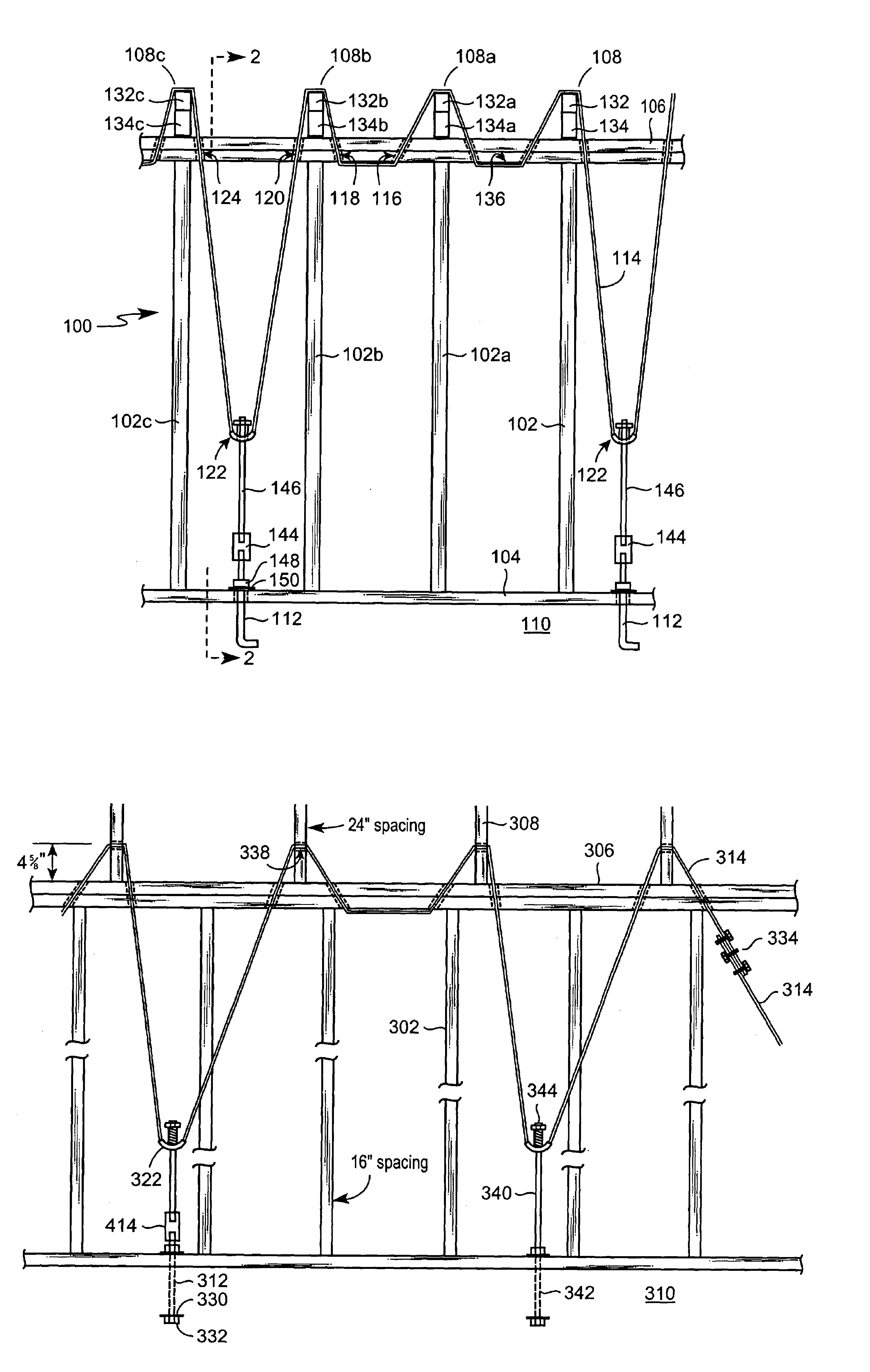
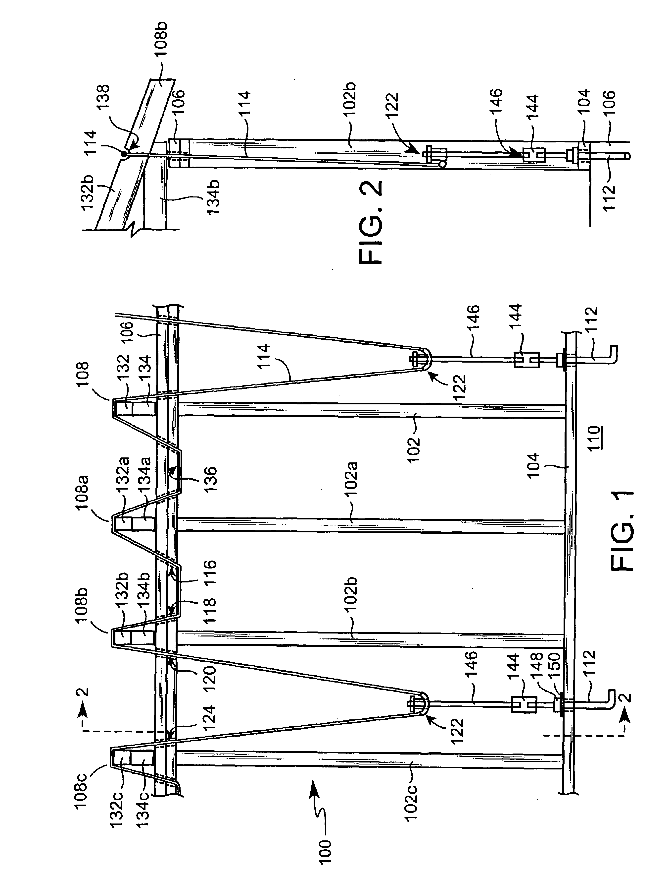
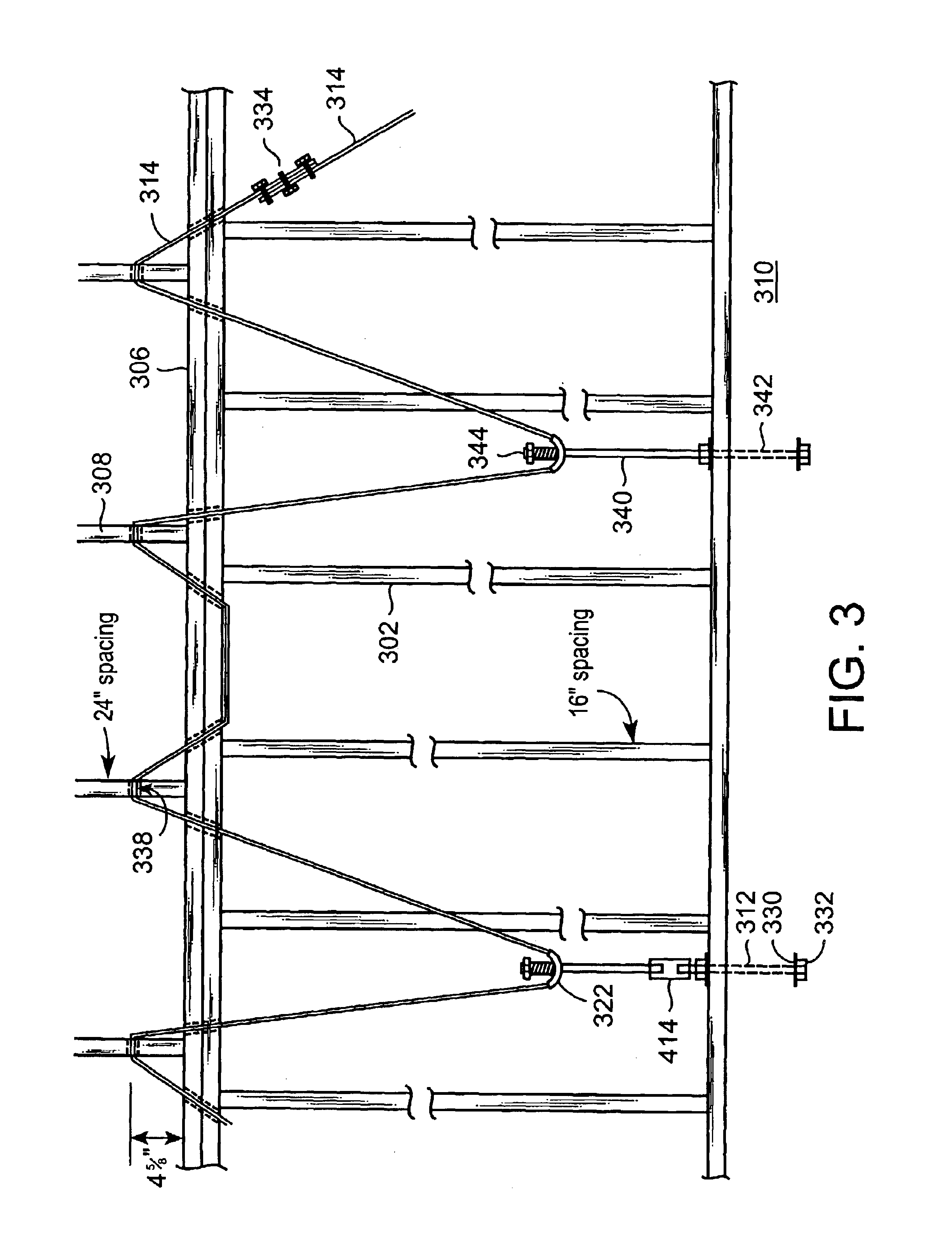
Referring now to the drawings, and more particularly to FIG. 1, one embodiment of a system 100 for securing wall framing and roofing members in a framed building against wind is shown. In a framed building, upright studs 102 extend vertically between a sill plate 104 and a top plate 106. The sill plate 104 rests on a foundation 110 which can be concrete or another suitable material. The foundation 110 can be of various types, including but not limited to a slab, footings, or blocks.

In a first embodiment of the invention, anchors 112 are secured in the building foundation 110. The anchor 112 is connected to a cable tensioner 122 through a rod 146, as described below in greater detail. The anchor 112 can be, for example, an anchor bolt such as a J-shaped bolt having a threaded end which extends out of the foundation 110. The anchor 112 could also be a straight bolt or other type of anchor bolt suitable for resisting upward tensile forces. If a straight bolt is used, a washer can be ar...


PUM


Abstract

A system and method for securing the wall framing and roof of a building structure against wind. A cable tensioner, located between two uprights of the wall framing and below the top plate, is attached to an anchor secured in the foundation. A cable extends over the first roofing member, under the top plate, over a second roofing member, through the cable tensioner, and over a third roofing member. In another embodiment, a cable tensioner has a vertical sleeve, a hollow tube affixed to the vertical sleeve, a rod extending through the vertical sleeve, and a nut threaded onto the nut for tensioning the cable.

Description

FIELD OF THE INVENTIONThis invention relates to a system for protecting a building structure against damage caused by winds, and more particularly to a cable system and method for securing roof members and wall framing.BACKGROUND OF THE INVENTIONIt is well known that high speed wind can do great damage to residential and commercial building structures, particularly in areas prone to hurricanes and other high wind storms. Each year hurricanes cause a considerable amount of damage to buildings, resulting in increased insurance rates. For this reason several states have enacted new building codes designed to insure that new structures are resistant to hurricane speed winds. For example the state of Florida recently enacted a new building code which requires all new buildings to comply with standards by the American Society of Civil Engineers and the Southern Building Code.Numerous systems have been tried for increasing the wind resistance of buildings. U.S. Pat. No. 5,448,861 to Lawson...

Claims


Application Information

Patent Timeline
Patent Type & Authority Patents(United States)
IPC IPC(8): E04B1/26E04G23/02E04H9/14E04B1/00E04B1/35
CPCE04B1/26E04H9/14E04G23/0218E04B2001/2684E04B2001/3583Y02A50/00
Inventor GADDIE, WILLIAM R.MOORE, BENNY K.
Owner GADDIE WILLIAM R
Why Eureka
Try Eureka