Sectional door with self-aligning hinges and method of assembly

a self-aligning, hinge technology, applied in the direction of door/window protective devices, wing accessories, manufacturing tools, etc., can solve the problems of affecting the ability to open or close the members, the hinges of living hinges tend to experience fatigue failure when used, and the hinges of multi-panel garage doors, which have presented pinching hazards at the junctur

Inactive Publication Date: 2005-01-18
OVERHEAD DOOR
View PDF24 Cites 24 Cited by
  • Summary
  • Abstract
  • Description
  • Claims
  • Application Information

AI Technical Summary

Benefits of technology

Therefore, an object of the present invention is to provide an upwardly acting sectional door having hinges that permit relative axial movement of adjacent sections. Another object of the present invention is to provide such a sectional door having hinges which permit a controlled extent of relative transverse movement of the adjacent sections through its range of articulation to prevent binding while accurately aligning adjacent sections in the planar closed position, a further object of the invention is to provide such a sectional door having a section spacing assembly to assure proper vertical separation of adjacent panels in the closed, planar position.

Problems solved by technology

Living hinges tend to experience fatigue failure when used repeatedly or when used over a wide pivot range.
Since the hinge is not self centering, this transverse movement may result in a misalignment that impairs the ability to open or close the members.
The movement may also permit unwanted “play” between the members.
Sectional doors, such as multi-panel garage doors, have presented a pinching hazard at the juncture between adjacent panels as the door closes and the panels shift to an aligned vertical position.
Prior art attempts to solve this problem have met with only limited success, sometimes presenting mechanical complexity or uneconomical designs.
Because the keyhole slots are out of phase when the hinge is finally connected to the panels, the pin cannot be removed.

Method used


Image

  • Sectional door with self-aligning hinges and method of assembly
  • Sectional door with self-aligning hinges and method of assembly
  • Sectional door with self-aligning hinges and method of assembly

Examples


Embodiment Construction

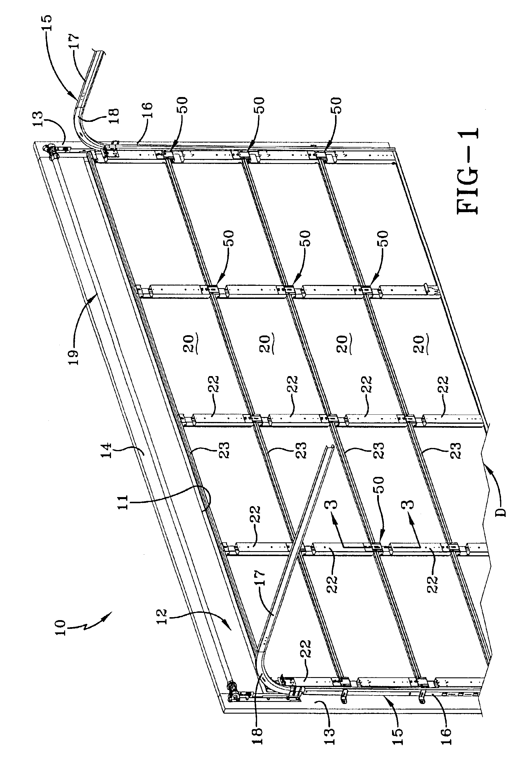
A door system according to the concepts of the present invention is generally indicated by numeral 10 in FIG. 1 of the drawings. Door system 10 includes a door, generally indicated at D, located within an opening 11 defined by a frame 12. Frame 12 includes a pair of spaced, vertical jambs 13 interconnected by a header 14 at their vertical upper extremity. Tracks, generally indicated by the numeral 15, are supported on frame 12 and guide the door D from a generally vertical closed position (FIG. 1) to a generally horizontal open position (not shown). To that end, each track 15 includes an upstanding vertical portion 16 supported on a jamb 13 and a generally horizontal portion 17 connected to the upstanding vertical portion 16 by an arcuate transition portion 18. To facilitate moving the door along the tracks 15, a counterbalance system, generally indicated by the numeral 19, may be employed and attached to the header 14. Since such counterbalance systems 19 are commonly used througho...


PUM


Abstract

A door system comprising, a plurality of sections pivotally joined to each other by a hinge assembly, the hinge assembly being pivotally supported on one of the sections and having a leg that extends from the one of the sections to an adjacent section to attach thereto, a stop assembly including a stop member extending forwardly from the leg toward a stop receiver carried on the one of the sections, whereby interaction of the stop member and the stop receiver ensure alignment of the sections.

Description

TECHNICAL FIELDIn general, the present invention relates to an upwardly acting sectional door. More particularly, the present invention relates to a door system having a hinge that permits self-adjusting movement of adjacent sections of the door. More specifically, the present invention relates to a door system having a hinge providing lateral movement of adjacent sections during articulation and vertical spacing in the closed planar position.BACKGROUND ARTMost hinges used on sectional garage doors are three-piece hinge assemblies that consist of two leaves and a pivot pin. These components of the hinge assembly can be made of metallic or non-metallic materials. The pivot hinge can be a tubular or solid shaft that is threaded through the two leaves and staked, flared, or bradded into place. The leaves are designed to interlace each other such that there is little or no movement along the axis of the pivot pin. Alignment on these hinges is critical in that they must be aligned both h...

Claims


Application Information

Patent Timeline
Patent Type & Authority Patents(United States)
IPC IPC(8): E05D15/16E05D15/24E05D11/00E05D5/06
CPCE05D15/242E05D5/06E05D11/00Y10T16/53613E05Y2900/106
Inventor MULLET, WILLIS J.MITCHELL, ALBERT W.BENNETT, III, THOMAS B.
Owner OVERHEAD DOOR
Why Eureka
Try Eureka