
Toggle bar link for conveyor and guideway pans and toggle bars, toggle bar sockets, safety elements, pans and assembly tools for toggle bar links

a technology of conveyor and guideway pans and toggle bars, which is applied in the direction of conveyors, metal-working machine components, large fixed members, etc., to achieve the effect of facilitating the cost-effective production of pans

Inactive Publication Date: 2005-01-18
DBT
View PDF5 Cites 6 Cited by
  • Summary
  • Abstract
  • Description
  • Claims
  • Application Information

AI Technical Summary

Benefits of technology

An aim of the present invention is to provide a toggle bar link which facilitates the cost effective production of pans and guideway pans including the associated elements for the toggle bar link.
With regard to the toggle bar for the toggle bar link according to the present invention it is advantageously provided that the first toggle bar plane of symmetry runs through the centre of the shaft between the toggle bar heads and the second plane of symmetry runs along the shaft and centrally through the toggle bar heads and the locking lugs, and further that the toggle bar heads and also the locking lugs are constructed mirror symmetrical to two planes of symmetry lying vertically to each other. The assembly of the toggle bar according to the present invention is made easier if the shaft has a waist located centrally between the shaft heads. This can not only serve as a gripping surface, but also in an advantageous manner eases the insertion of the toggle bar into the toggle bar sockets of pans abutting each other.
So that the toggle bar on the one hand can be distinguished in respect of production engineering by simple construction and on the other is able to accept without difficulty the demands of bending, pressure, tension and shear, the toggle bar has, symmetrically to the second plane of symmetry, a toggle bar head in each case and tapers continuously from the first plane of symmetry or the toggle bar heads outwards and downwards. To limit the amount by which two abutting conveyor pans can be pulled apart in the axial direction, the toggle bar heads can taper conically towards the shaft by means of inclined shoulder surfaces, whereby they co-operate advantageously with correspondingly formed inclined abutment shoulders in the toggle bar socket side walls. It is further provided in accordance with the present invention that the locking lugs and locking heads on both shaft ends are formed identically to each other.
Preferably, the securing elements for the toggle bar links according to the present invention comprise an elongate plate, which has two holes arranged symmetrically to the centre line of the plate to accept detachable, deformable securing bolts which can be keyed into the cut-outs of the socket cut-outs. The symmetrical construction of the securing elements here also prevents the possibility of their being fitted the wrong way around. The assembly of the securing elements can be effected by elastic deformation of the securing bolts. It is, however, advantageously provided that the holes are provided with counterbores on each side of the plate surface, so that not only is the deformation of the securing bolts made easier, but also, because of the geometry of the counterbores, the securing bolts can be completely pushed into the holes only after correct positioning of the securing elements.

Problems solved by technology

Furthermore, owing to the symmetrical construction of the individual elements, it is not possible that, for instance, the toggle bar is assembled incorrectly in the toggle bar socket, that underground in a repair of the conveyor pans the wrong toggle bar socket is incorrectly assembled to the conveyor pan side walls or even that the securing elements are fitted the wrong way round.

Method used


Image

  • Toggle bar link for conveyor and guideway pans and toggle bars, toggle bar sockets, safety elements, pans and assembly tools for toggle bar links
  • Toggle bar link for conveyor and guideway pans and toggle bars, toggle bar sockets, safety elements, pans and assembly tools for toggle bar links
  • Toggle bar link for conveyor and guideway pans and toggle bars, toggle bar sockets, safety elements, pans and assembly tools for toggle bar links

Examples


Embodiment Construction

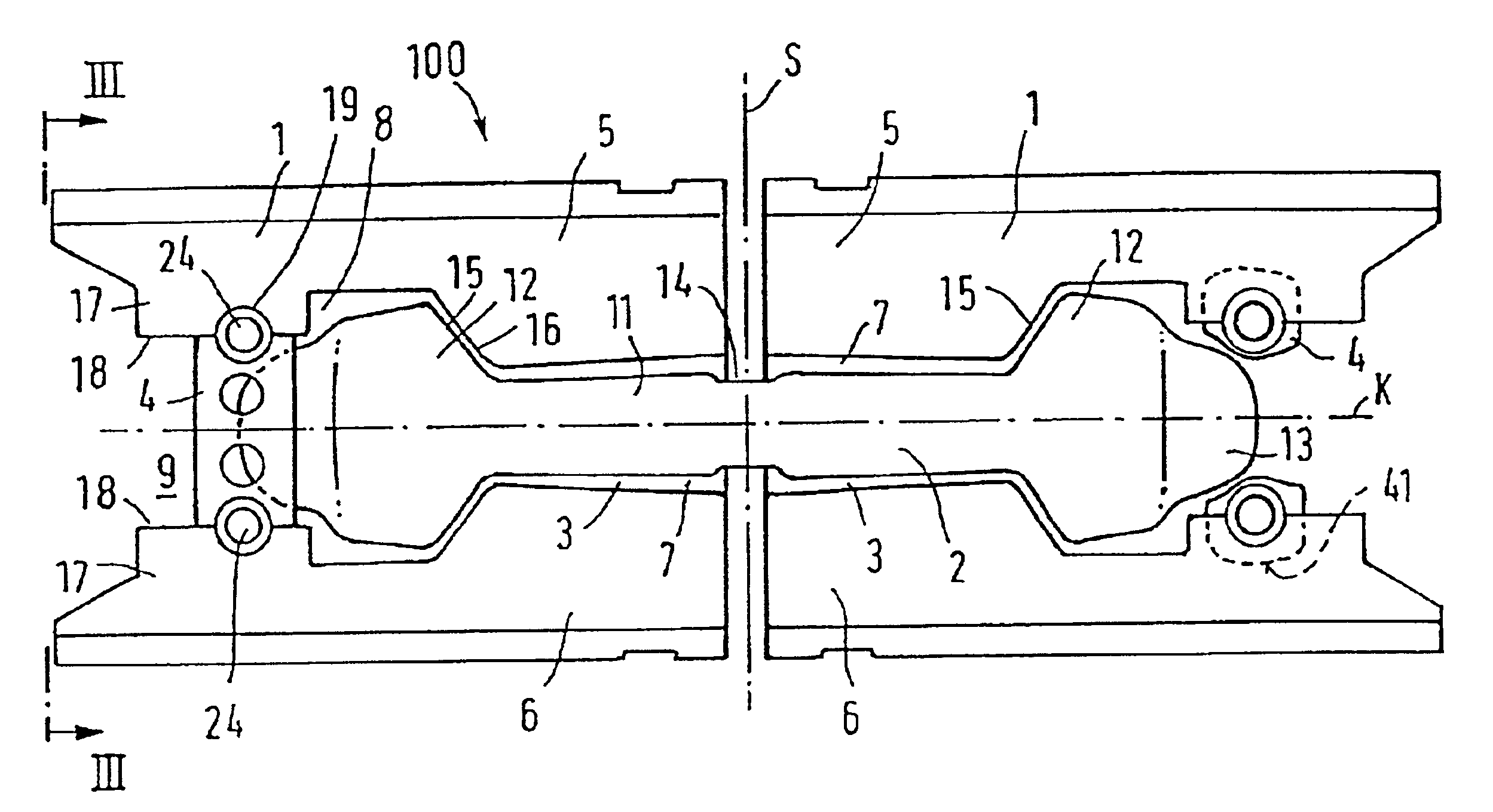
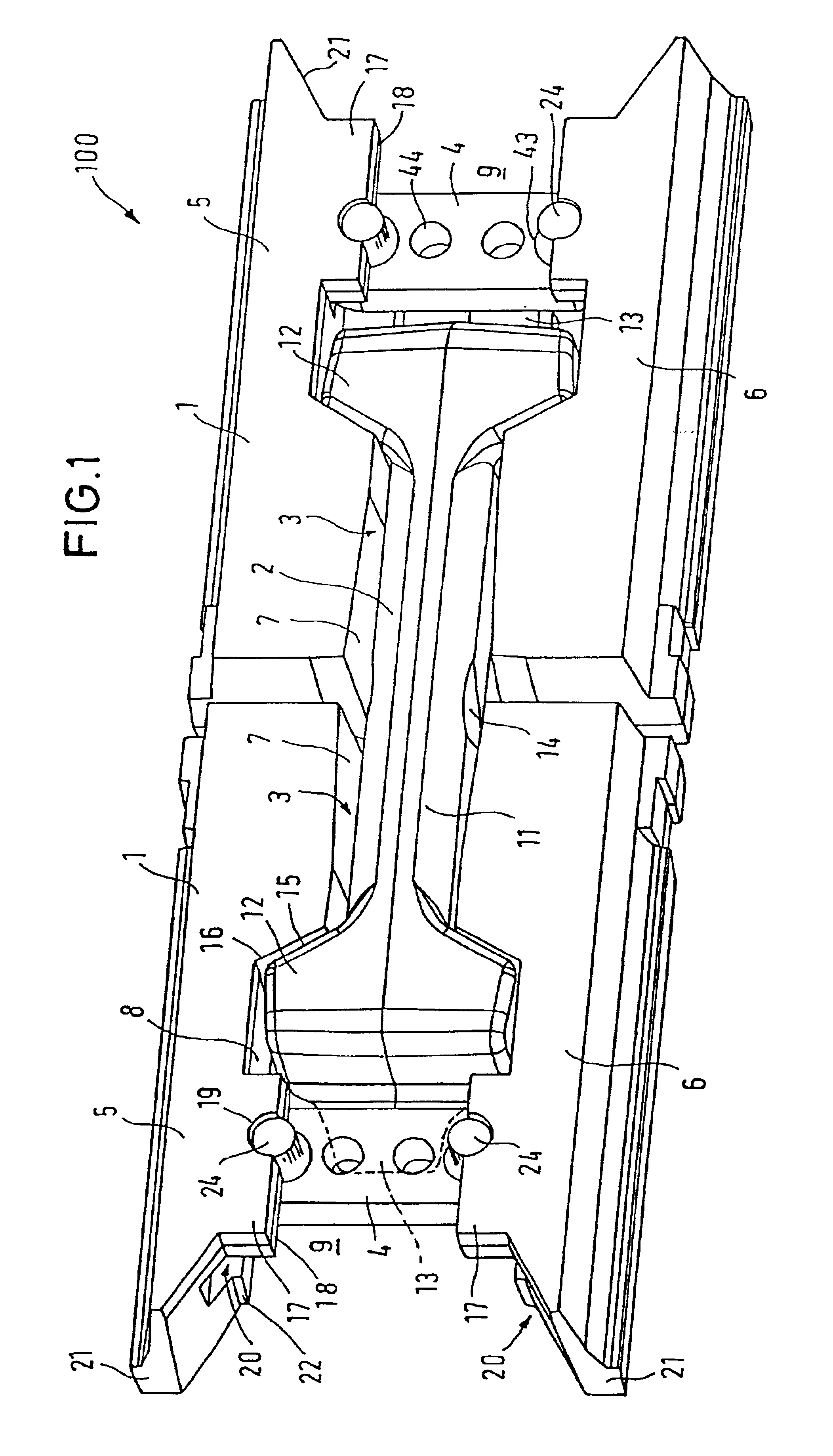
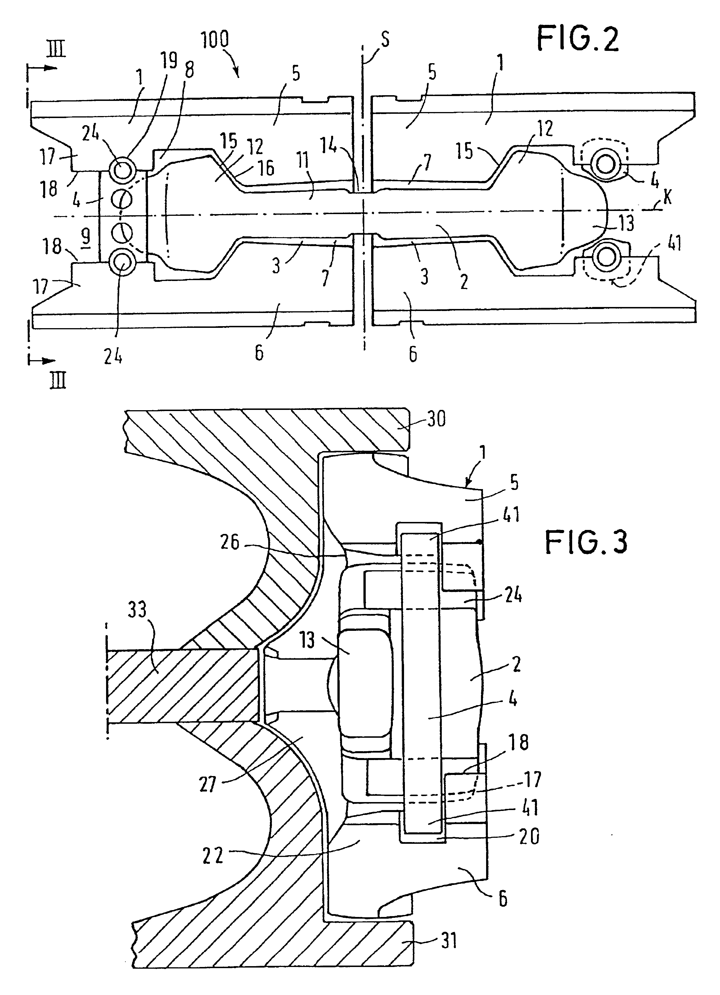
FIGS. 1, 2 and 3 show a complete toggle bar link 100 for the coupling of two conveyor pans. The toggle bar link 100 is formed from two toggle bar sockets 1, identically constructed and assembled to the coupling ends of the conveyor pans as mirror images of each other, a single piece toggle bar 2 and two locking plates 4, with which the toggle bar 2 is secured against falling out to the side within the toggle bar socket cut-outs 3 of the toggle bar sockets 1. The toggle bar sockets 1 are assembled mirror-symmetrically to the plane of symmetry S and to the conveyor pans at the side, so that the toggle bar 2 is inserted from the side into the socket cut-outs 3 which are open to the sides. The toggle bar sockets 1 have two toggle bar socket side parts 5, 6, which are arranged mirror-symmetrically to the first toggle bar socket plane of symmetry K (FIG. 2), and between which the socket cut-outs 3 are formed, and which are only joined together at the socket base 26 (FIG. 3) as will be exp...


PUM


Abstract

In a toggle bar link (100) for conveyor pans of conveyors or guideway pans of extraction machine guideways, with toggle bar sockets (1) arranged at the sides of the pans in whose socket cut-outs (3) a toggle bar can be inserted and retained by securing elements (4), both the toggle bar (2) and the securing elements (4) as well as the toggle bar sockets (1) are constructed intrinsically symmetrically and the toggle bar sockets (1) are arranged symmetrical to a plane of symmetry (S) running through the joint between the pans. Owing to the symmetrical construction of the individual parts they can not only be produced simply but also no orientation problems are posed in the assembly of the individual parts.

Description

THE FIELD OF THE INVENTIONThe present invention relates to a toggle bar link for conveyor pans of conveyors, guideway pans of mining machine tracks and similar, with toggle bar sockets arranged at the sides of the pans, open to the side, in whose cut-outs a toggle bar can be inserted whose heads are joined in one piece by a shaft which is smaller in cross section and whose heads have locking lugs to secure the toggle bar in the toggle bar socket cut-outs by means of detachable securing elements. Since the toggle bar link has toggle bar sockets and toggle bars which are arranged on the pans and since detachable securing elements must be assembled for securing the toggle bars, the present invention also relates to toggle bar sockets, toggle bars, securing elements, the pan itself as well as an assembly tool for a corresponding toggle bar link.Toggle bar links are primarily provided as conveyor pan links in scraper chain conveyors, which are preferred for use in underground mining oper...

Claims


Application Information

Patent Timeline
Patent Type & Authority Patents(United States)
IPC IPC(8): B65G19/28B65G19/00
CPCB65G19/287
Inventor SCHMIDT, SIEGFRIEDWIRTZ, JORG
Owner DBT
Learn More