Fail-safe aircraft engine mounting system

a technology for aircraft engines and mounting systems, applied in the field of mounting systems, can solve the problems of significant weight penalties for dual thrust links

Active Publication Date: 2005-01-18
GENERAL ELECTRIC CO
View PDF15 Cites 131 Cited by
  • Summary
  • Abstract
  • Description
  • Claims
  • Application Information

AI Technical Summary

Benefits of technology

Briefly stated, in accordance with one aspect of the present invention a mounting system is provided for mounting an aircraft engine to an aircraft. The mounting system includes a first mount member including a first fail-safe clevis defined by a pair of first clevis ears having opposed faces that are spaced from each other for receiving therebetween a first fail-safe lug carried by an engine. The first fail-safe lug has outer surfaces that are each spaced from respective first clevis ear surfaces to define first fail-safe clevis gaps. A second mount member includes a second fail-safe

Problems solved by technology

However, dual thrust links impose a significant wei

Method used


Image

  • Fail-safe aircraft engine mounting system
  • Fail-safe aircraft engine mounting system
  • Fail-safe aircraft engine mounting system

Examples


Embodiment Construction

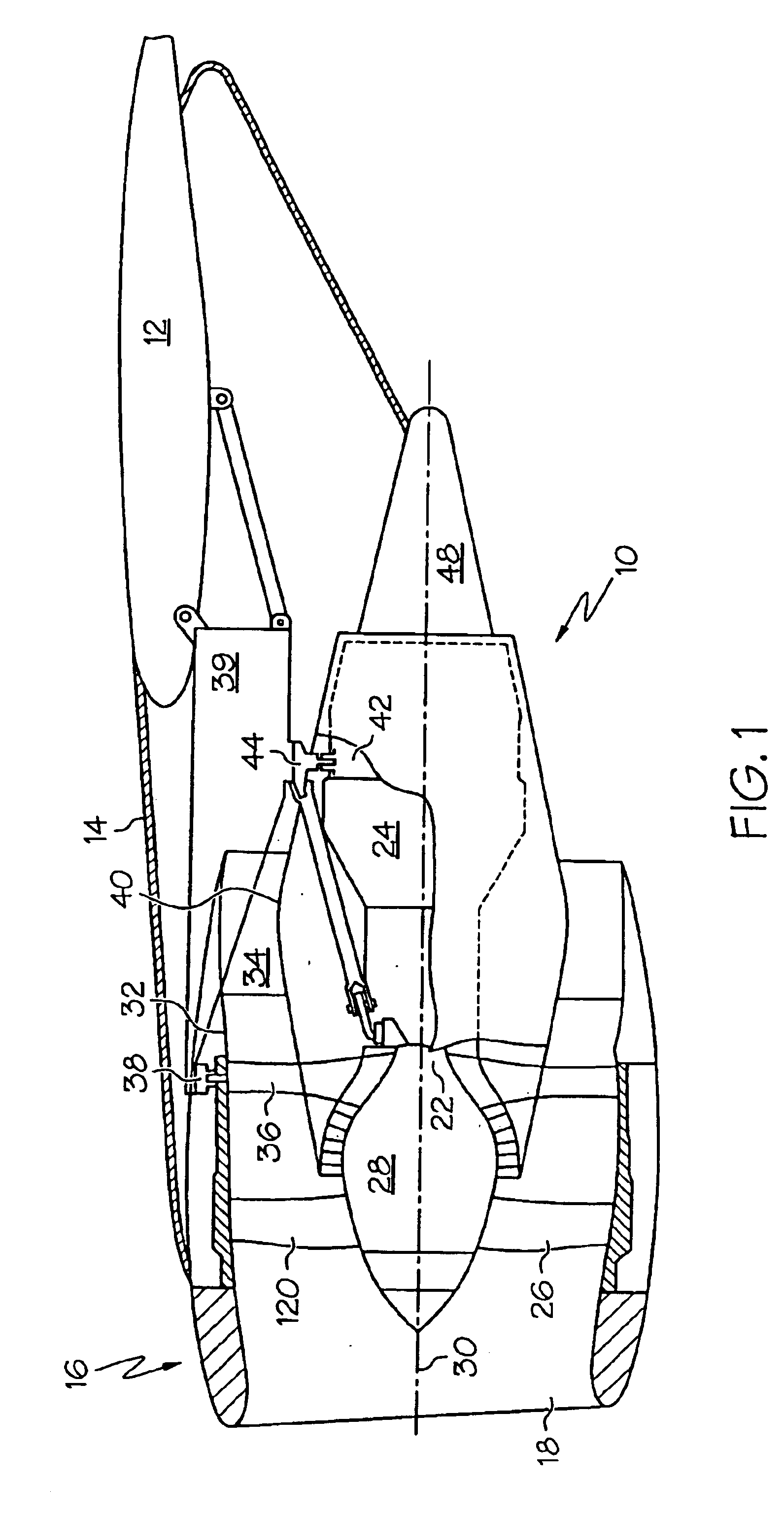
Referring now to the drawings, and particularly to FIGS. 1 and 2 thereof, there is shown an aircraft engine 10 and an associated mounting structure for mounting the engine to an aircraft wing 12 in a typical under-wing engine mounting arrangement. Aircraft wing 12 shown in FIG. 1 carries engine 10, which can be a turbofan engine, as shown, or, alternatively, a turbojet engine. Engine 10 is supported from wing 12 by an engine support structure that is enclosed within an aerodynamically-shaped pylon 14 carried by wing 12. Positioned at the forward, inlet end of engine 10 is a forward nacelle 16 in the form of an aerodynamically-shaped, annular shroud that defines an inlet through which air enters engine 10.

Engine 10 includes a front-mounted fan 20 that is coupled with and driven by a drive shaft 22 forming part of core gas turbine engine 24. Fan 20 includes a plurality of circumferentially-spaced, radially-extending fan blades 26 that are carried on a rotatable fan hub 28 that is conn...


PUM


Abstract

A fail-safe lug is carried by an engine frame member and receives a clevis carried by an engine mount member. The mount member includes side links that transmit transverse loads between the engines and the airframe and a thrust link that transmits axial, engine thrust loads between the engine and the airframe. A fail-safe pin is carried by the clevis and has an outer diameter that is smaller than an aperture in the lug and through which the pin passes, so that no loads are imposed on the fail-safe pin in normal operation. When one or more of the links are no longer capable of transmitting loads, the fail-safe arrangement becomes operative to accommodate the loads transmitted between the engine and the airframe.

Description

BACKGROUND OF THE INVENTIONThe present invention relates to a mounting system for mounting an aircraft engine to an aircraft. More particularly, the present invention relates to a fail-safe engine mounting system that transmits between the engine and aircraft axial thrust loads, as well as lateral and vertical loads, in the event of a failure of the main load-transmitting elements.Aircraft engines, such as turbojet engines and turbofan engines, are mounted on an aircraft in such a way as to transmit to the airframe of the aircraft engine thrust loads to propel the aircraft. At the same time, the engine-to-airframe mounting system must also be capable of sustaining pitch, roll, yaw, and other loads that pass between the engine and airframe. Such loads are the result of aircraft maneuvers, and they impose upon the engine axial loads that extend in the direction of the engine longitudinal axis, as well as loads that extend in a direction transverse to the engine longitudinal axis.Turbo...

Claims


Application Information

Patent Timeline
IPC IPC(8): B64D27/26B64D27/00B64D27/16F01D25/24F02C7/20
CPCB64D27/26Y02T50/44B64D2027/268B64D2027/266Y02T50/40
Inventor MANTEIGA, JOHN ALANWILUSZ, CHRISTOPHER JAMESDYKHUIZEN, CORNELIUS HARM
Owner GENERAL ELECTRIC CO
Why Eureka
Try Eureka