Smoothly blended optical surfaces

a technology of optical surfaces and optical surfaces, applied in the field of optical design of lens surfaces and ophthalmic lens manufacture, can solve the problems of complicated mathematical techniques and associated computer power, inability to achieve high-order algorithms, so as to achieve the effect of numerical techniques, reducing the number of iterations, and reducing the number of optical surfaces

Inactive Publication Date: 2005-01-18
BAUSCH & LOMB INC
View PDF13 Cites 55 Cited by
  • Summary
  • Abstract
  • Description
  • Claims
  • Application Information

AI Technical Summary

Benefits of technology

The invention is thus advantageous in that a complex three-dimensional surface can be represented by a plurality of simple two-dimensional cross sectional profiles. Surface accuracy can be controlled by sampling greater or fewer azimuthal profiles. Therefore, in blending non-rotationally symmetric surfaces to rotationally symmetric surfaces, for example, each cross-section may be addressed individually. Such an approach eliminates the difficult three-dimensional mathematics that would be required otherwise. Thus, the true blending surface will be a result of the many blends that are applied in each meridional cross-section; it will not exist as an explicit geometric entity in and of itself Furthermore, the invention is applicable to the smooth and continuous blending of multiple generic surfaces. According to the invention, minimal computing time is required to obtain a unique solution for each blending surface, eliminating iterations and numerical techniques.

Problems solved by technology

Alternatively, complicated mathematical techniques and associated computer power are required for complex surface shapes such as those of custom contact lenses, for example.
In this case, a more complicated, higher order algorithm is required.
Although the Ducharme patent is not expressly limited to rotationally symmetric surfaces, the practical application may be so limited.
Furthermore, Ducharme's spline surfaces do not describe the optics of the lens.

Method used


Image

  • Smoothly blended optical surfaces
  • Smoothly blended optical surfaces
  • Smoothly blended optical surfaces

Examples


Embodiment Construction

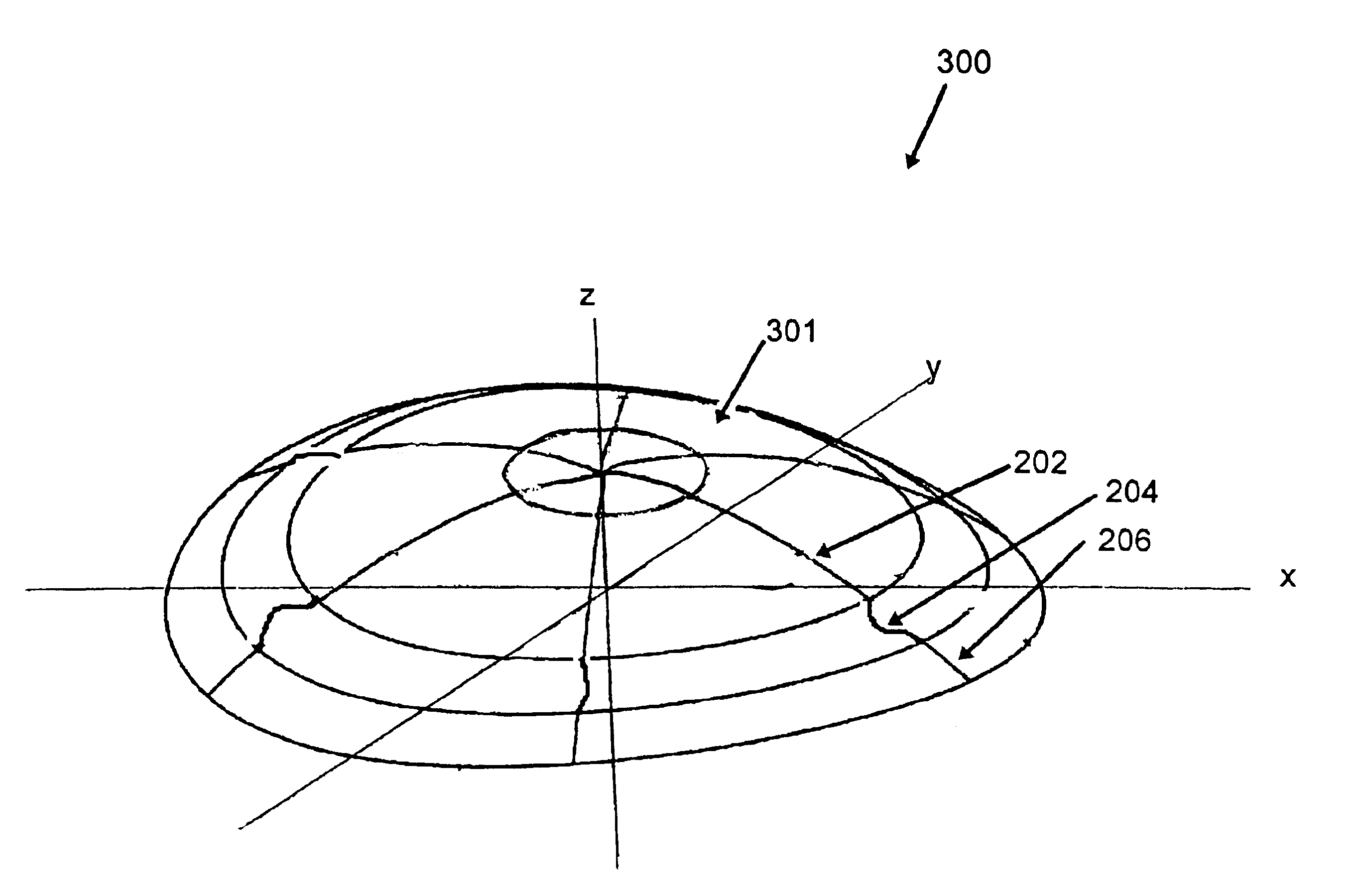
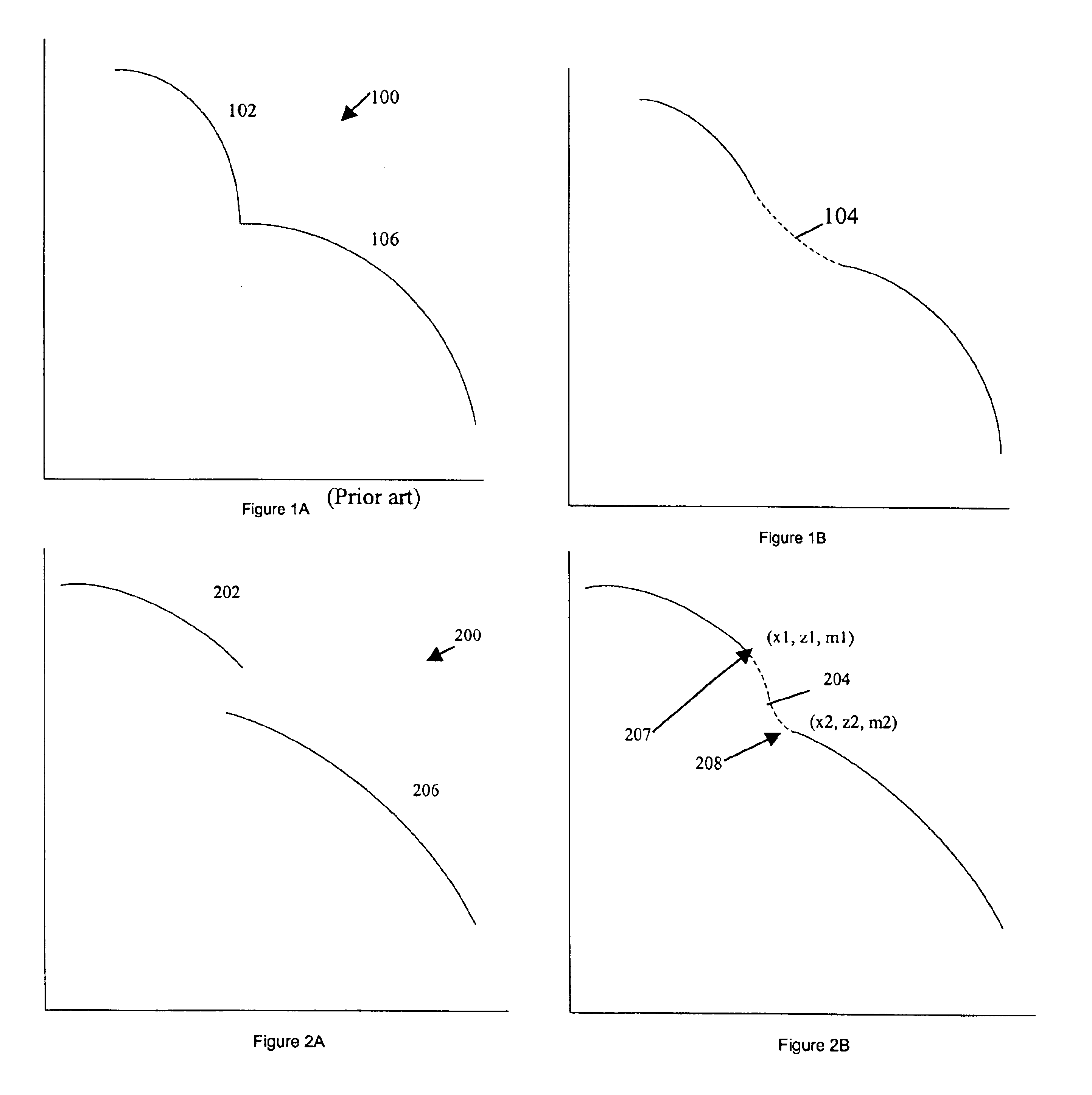
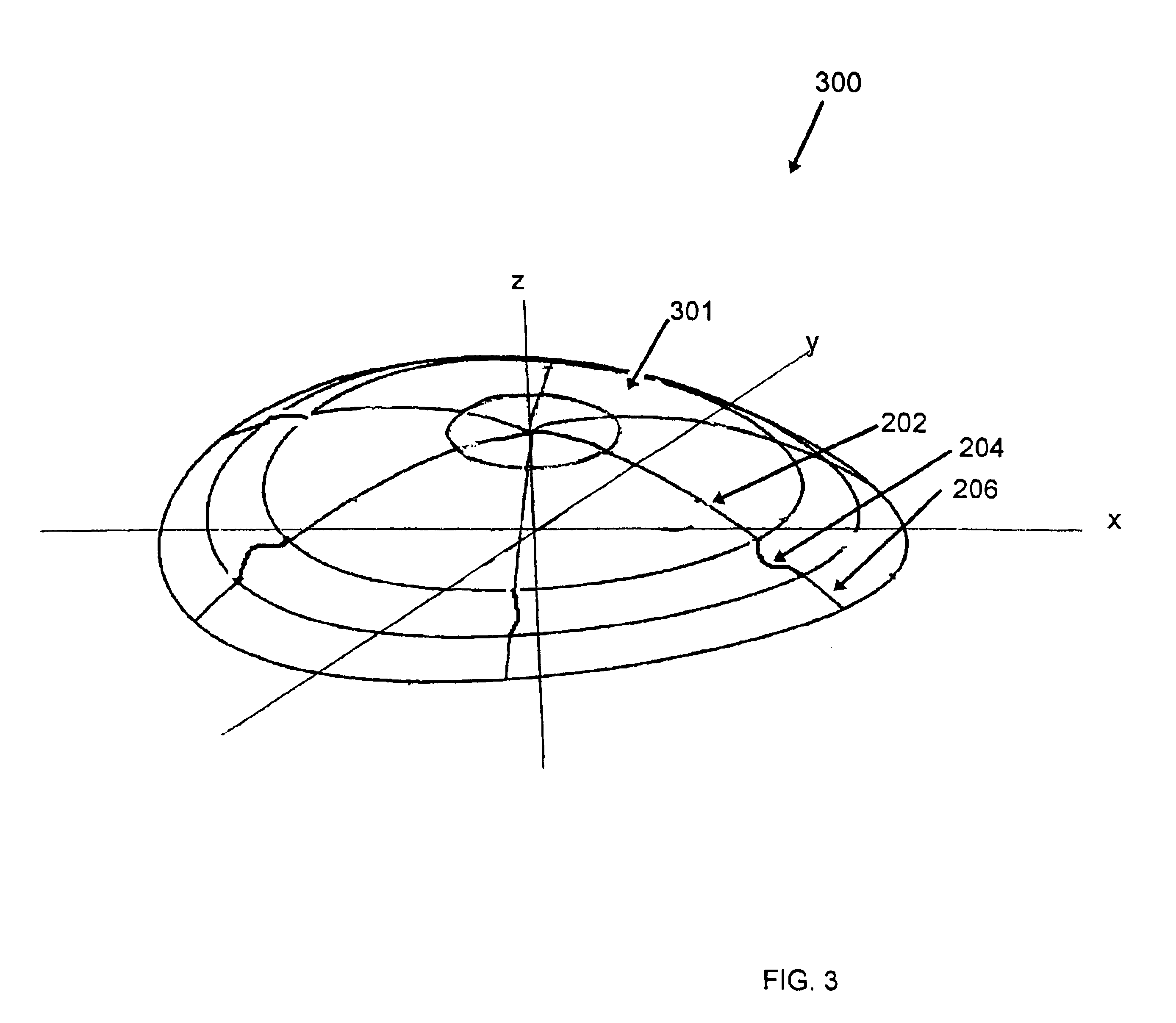
With reference to FIGS. 2A, 2B, and 3, an embodiment of the invention is directed to an optical lens and, preferably, to an ophthalmic custom contact lens 300 for vision correction, in which the anterior and / or posterior surface of the lens is ultimately a non-rotationally symmetric surface 301. FIG. 2A illustrates a meridional cross sectional profile 200 of two disparately shaped, radially adjacent zones 202, 206 that must be incorporated into the surface 301 of the lens. As shown in FIG. 2B, dotted line 204 represents the cross sectional profile of a blend zone 204 that smoothly and continuously joins disparate zones 202 and 206. According to the invention, the blend zone profile 204 is defined by a single third-order polynomial expressed by equation (1) as follows:

z(x)=a1+a2·x+a3·x2+a4·x3  (1)

where z(x) is the sag of the blend profile. It is expected that the geometry of each of the zone profiles 202, 206 is quantitatively known, thus the end point x1, the sag value z1, and the s...


PUM


Abstract

Apparatus, products, and methods are described that relate to blending various disparate optical surfaces in a smooth and continuous manner. In cross section, the two disparate surfaces are represented as meridional profiles. A blend zone profile is described by a single third-order polynomial. In the case of rotationally symmetric optics, one cross-section suffices for the description of the entire surface. In the case of non-rotationally symmetric optics, an increased number of cross-sections are necessary to produce the desired three-dimensional surface, thus meridional profiles are calculated at selected azimuthal locations to describe the full surface.

Description

BACKGROUND OF THE INVENTION1. Field of the InventionThe invention is generally directed to the field of optical design of a lens surface and ophthalmic lens manufacture, and more specifically to blending disparate optical surfaces smoothly and continuously in an optical lens.2. Description of Related ArtContact lenses have been around for many years. Lens surfaces that were once limited to simple spherical profiles have given way to surface shapes that are now limited only by the ability to physically impart a surface topology described by any of a variety of complex mathematical expressions. Over the last ten years or so, toric surfaces have been put on contact lenses for the correction of astigmatism. Multifocal lenses have surfaces with various power zones for near, intermediate, and far distance viewing, while some contact lenses rely on Fresnel zones or diffractive effects for guiding light through the lens.Wavefront sensors now routinely allow doctors to measure higher order a...

Claims


Application Information

Patent Timeline
Patent Type & Authority Patents(United States)
IPC IPC(8): G02C7/04
CPCG02C7/041G02C7/04
Inventor RICHARDSON, GARY A.
Owner BAUSCH & LOMB INC
Why Eureka
Try Eureka