
Automated mirroring of components

a technology of components and mirroring, applied in the field of automatic mirroring of components, can solve the problems of inability to create a truly incorrect material bill generation, and inability to produce a true mirrored part in the context of an assembly

Inactive Publication Date: 2005-01-18
DASSAULT SYST SOLIDWORKS CORP
View PDF5 Cites 42 Cited by
  • Summary
  • Abstract
  • Description
  • Claims
  • Application Information

AI Technical Summary

Benefits of technology

The invention is a method for creating a mirrored version of a three-dimensional object. This involves receiving data to select a component of the object, analyzing different orientations for reproducing the component, and creating a new component based on the position of the original component. The new component can be a replicated or reflected version of the original component. The method can be implemented in computer systems and can be useful for creating bill of materials for components of an object. The technical effect of the invention is to provide a way for accurately and efficiently creating mirrored versions of three-dimensional objects.

Problems solved by technology

However, SolidWorks 2000 is not capable of creating a truly mirrored part in the context of an assembly.
A common problem encountered by design engineers that generate mirrored components is producing a correct bill of materials for the assembly.
Some CAD systems may not make the distinction that truly mirrored parts are unique and may produce an incorrect bill of materials.
Another situation that causes an incorrect bill of materials to be generated arises when one part represents an entire subassembly.
In order to create a mirrored component of an entire subassembly, some commercially available products require a design engineer to create one part that consists of the entire subassembly, and therefore, an erroneous bill of materials may be generated that represents the mirrored subassembly as one part rather than numerous parts.
Such an automated mechanism would save the design engineer a considerable amount of time and effort during the 3D modeling process.

Method used


Image

  • Automated mirroring of components
  • Automated mirroring of components
  • Automated mirroring of components

Examples


Embodiment Construction

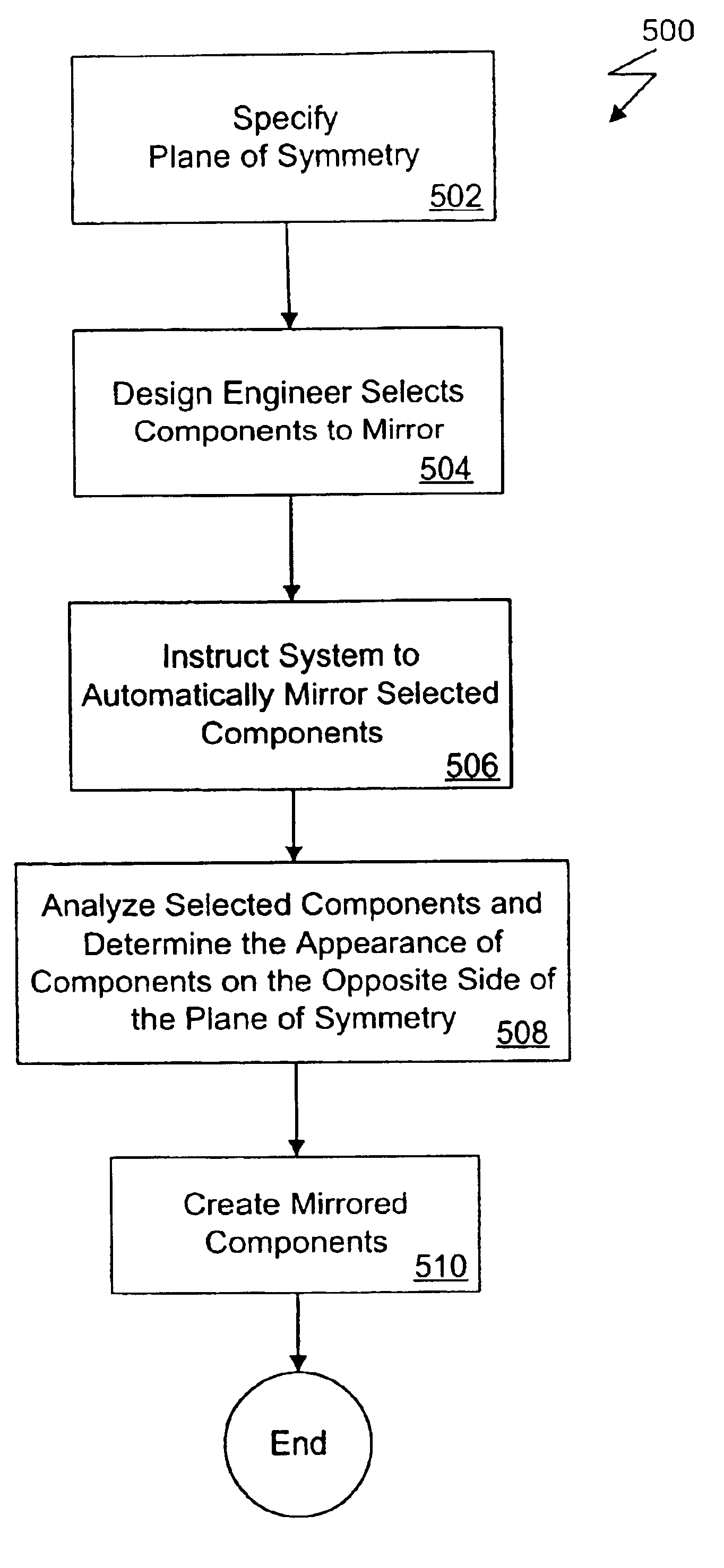
The present invention automatically creates mirrored components (i.e., parts and subassemblies). Mirrored components may consist of replicated components, truly mirrored components, or combinations thereof. The design engineer may select which components to re-use in an assembly and may specify whether to create a replicated component or a truly mirrored component for each original component selected. Additionally, the present invention may automatically determine from which components to create replicated components and from which components to create truly mirrored components, without user intervention.

The present invention automatically copies and positions a replicated component in such a way that the location of the replicated component is symmetric to the location of the original component; whereas, a truly mirrored component is reflected about a plane of symmetry and takes the form of a left-hand version of a right-hand component. The present invention also preserves the hier...


PUM


Abstract

Automatically generating components of an object modeled in a three-dimensional modeling space by a computer aided design system includes positioning a plane in the three-dimensional modeling space to (i) logically subdivide the modeling space into a first division that includes an existing component and a second division in which a reproduction of the existing component is to be located and (ii) to define a reference geometry for creation of the reproduction of the existing component. A number of geometrically transformed components are computed by applying a series of different transformations to the existing component such that each transformed component has a different orientation. A reproduction of the existing component is constructed such that the existing component and the reproduction are symmetrical to each other with respect to the plane.

Description

BACKGROUND OF THE INVENTIONComputer-aided design (CAD) software allows a user to construct and manipulate complex three-dimensional (3D) models of assembly designs. A number of different modeling techniques can be used to create a model of an assembly. These techniques include solid modeling, wire-frame modeling, and surface modeling. Solid modeling techniques provide for topological 3D models, where the 3D model is a collection of interconnected edges and faces, for example. Geometrically, a 3D solid model is a collection of trimmed surfaces. The trimmed surfaces correspond to the topological faces bounded by the edges. Wire-frame modeling techniques, on the other hand, can be used to represent a model as a collection of simple 3D lines, whereas surface modeling can be used to represent a model as a collection of exterior surfaces. CAD systems may combine these, and other, modeling techniques, such as parametric modeling techniques.Parametric modeling techniques can be used to defi...

Claims


Application Information

Patent Timeline
Patent Type & Authority Patents(United States)
IPC IPC(8): G06T17/00G06T17/40
CPCG06T19/20G06T2219/2016G06T2200/24G06F30/17
Inventor RAJKUMAR, PARAPURA T.HALLER, KIRKGIBSON, MARK G.LI, HEUNG-WING
Owner DASSAULT SYST SOLIDWORKS CORP
Learn More