

Method for trapping raster data in a run-length encoded form
- Summary
- Abstract
- Description
- Claims
- Application Information
AI Technical Summary
Problems solved by technology
Method used
Image

Examples
example 1
We consider the case where the user specifies a trap radius of 1. Run-length encoded data consisting of constant color runs is sent to the trapping module for misregistration corrections. Since the trap radius is one, the input and output scanline buffers will collect two scanlines each. The set of scanlines under consideration in the scanline buffers is shown schematically in FIG. 9.
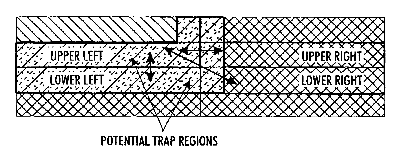
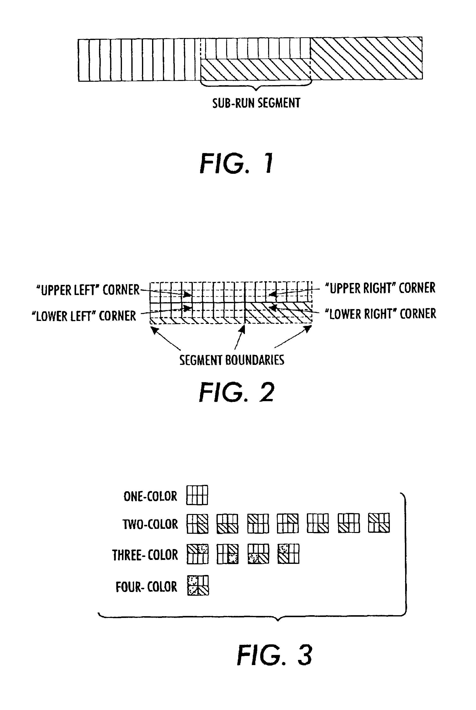
Inspection of the input scanline buffer reveals that segment boundary appears on the topmost scanline, at the intersection between the red and green runs. The geometry will be determined by the run colors that appear at this segment boundary: upper left=red, upper right=green, lower left=blue, lower right=blue. The geometry for this example would be a split-upper, one of the 13 specified geometries from FIG. 3. Since the upper left and the upper right colors are different, the trap generator will be consulted. In this example, it is assumed the color returned by the trap generator is a brownish-green ti...
example 2
We consider the case where the user specifies a trap radius of 2. Run-length encoded data consisting of constant color runs is sent to the trapping module for misregistration corrections. Since the trap radius is two, the input and output scanline buffers will collect four scanlines each. The set of scanlines under consideration in the scanline buffers is shown schematically in FIG. 13.
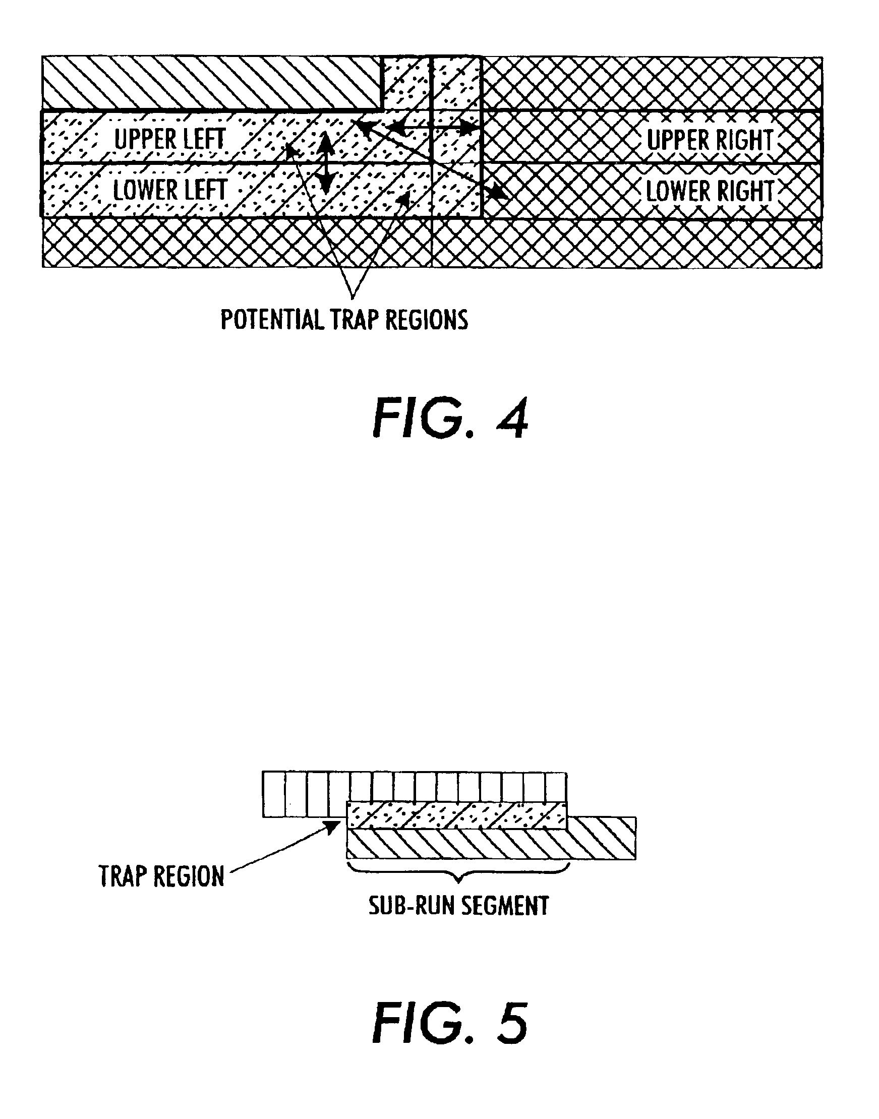
Inspection of the input scanline buffer reveals that a segment boundary appears at the same fast position both on the first and second scanlines, at the intersection between the red and blue runs. The geometry will be determined by the run colors that appear at this segment boundary: upper left=red, upper right=blue, lower left=blue, lower right=blue. The geometry for this example would be a corner upper-left (since only the upper left corner is a different color), one of the 13 specified geometries from FIG. 3. Since the upper left and the upper right colors are different, the trap generator will be ...
example 3
We consider the case where the user specifies a trap radius of 2. Run-length encoded data consisting of constant color runs and smooth gradation runs (sweeps) is sent to the trapping module for misregistration corrections. Since the trap radius is two, the input and output scanline buffers will collect four scanlines each. The set of scanlines under consideration in the scanline buffers is shown schematically in FIG. 19.
Inspection of the input scanline buffer reveals that a segment boundary appears at the same fast position both on the first and second scanlines, at the intersection between the sweep and blue runs. The geometry will be determined by the run colors that appear at this segment boundary: upper left=red (the rightmost pixel value of the sweep in the second scanline), upper right=blue, lower left=blue, lower right=blue. The geometry for this example would be a corner upper-left (since only the upper left corner is a different color), one of the 13 specified geometries fr...
PUM
 Abstract
Description
Claims
Application Information