Electronic voting method and system and recording medium having recorded thereon a program for implementing the method

a technology of electronic voting and recording medium, applied in the field of electronic voting system, can solve the problems of lack of usability of the conventional system from the voter's point of view, and achieve the effects of ensuring voter privacy, robustness against system dysfunction, and simple and convenien

Inactive Publication Date: 2005-01-18
NIPPON TELEGRAPH & TELEPHONE CORP
View PDF2 Cites 48 Cited by
  • Summary
  • Abstract
  • Description
  • Claims
  • Application Information

AI Technical Summary

Benefits of technology

It is therefore an object of the present invention to provide a simple and convenient electronic voting system and method which ensure voter privacy in making a complaint abo...

Problems solved by technology

With this method, however, it is necessary for the voter Vi to confirm the registration of his cipherteXt xi by checking a list of ballots that is published...

Method used


Image

  • Electronic voting method and system and recording medium having recorded thereon a program for implementing the method
  • Electronic voting method and system and recording medium having recorded thereon a program for implementing the method
  • Electronic voting method and system and recording medium having recorded thereon a program for implementing the method

Examples


embodiment 1

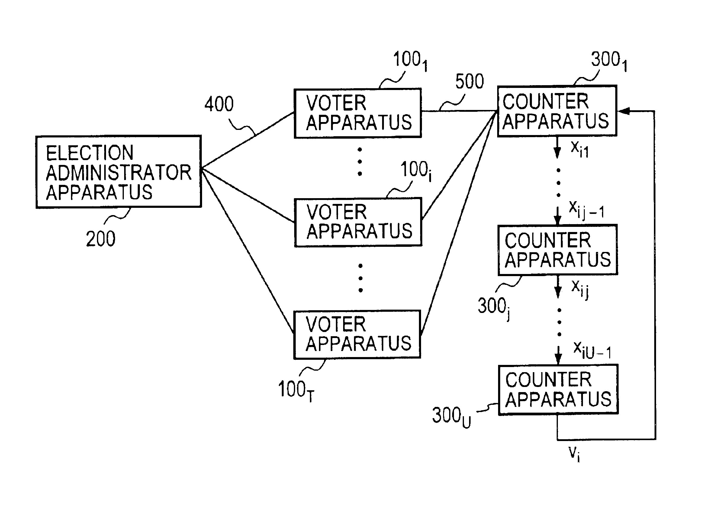
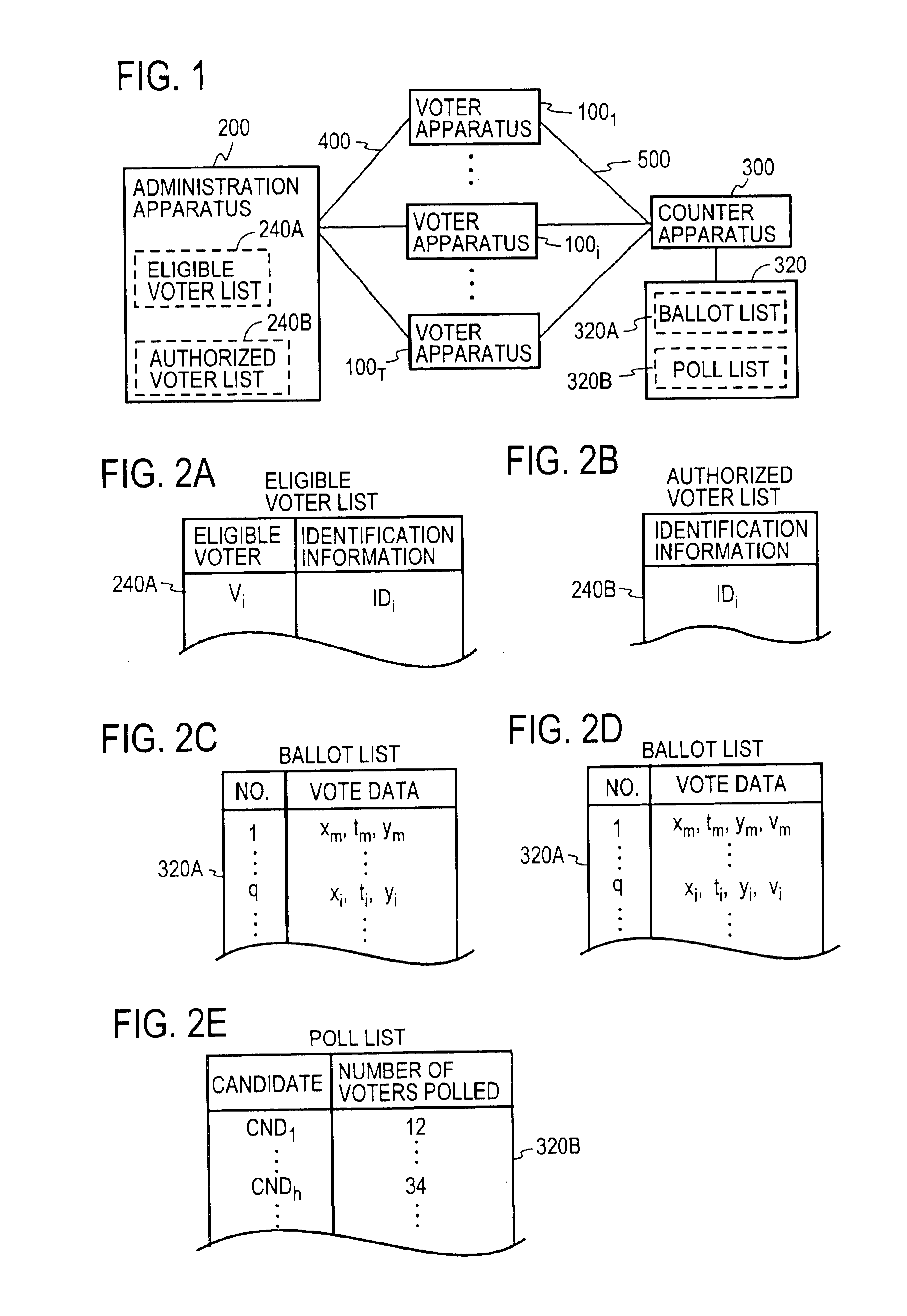
FIG. 1 schematically illustrates the general configuration of the voting system according to the present invention. Apparatuses 100 of T voters Vi (where i=1, . . . , T) (which apparatuses 100 will hereinafter be referred to as voter apparatuses) are each connected to an apparatus 200 of an election administrator A (which apparatus 200 will hereinafter be referred to as an administrator apparatus) and a apparatus 300 of a counter C (which apparatus 300 will hereinafter be referred to as a counter apparatus) via nonanonymous and anonymous communication channels 400 and 500, respectively. When sending information to the administrator A via the nonanonymous communication channel 400, the voter Vi adds the information with sender information indicating who the sender is, for example, his name Vi or identification information IDi. In the case of sending information to the counter C via the anonymous communication channel 500, the voter Vi adds no sender information. The counter C publish...

embodiment 2

FIG. 7 schematically illustrates the general configuration of a voting system according to a second embodiment of the present invention. This embodiment is identical with the first embodiment in that every voter apparatus 100 is connected to the administrator apparatus 200 through the communication channel 400 and to one counter apparatus through the anonymous communication channel 500, but structurally differs in that a plurality of counter apparatuses (hereinafter referred to as distributed counter apparatuses) 300j (where j=1, . . . , U). The distributed counter apparatus 3001 decrypts ciphertexts xi from all voters to generate xi1 and sends it to the next distributed counter 3002; similarly, a j-th distributed counter apparatus 300j decrypts decrypted data xij-1 received from the immediately preceding distributed counter apparatus 300j-1 to generate decrypted data xij and sends it to the next distributed counter apparatus 300j+1. The vote content vi is obtained for the first tim...

third embodiment

FIG. 9 illustrates the general configuration of a voting system according to a third embodiment of the present invention. In this embodiment each voter apparatus 100i (where i=1, . . . , T) is made connectable to all the distributed counter apparatuses 3001 to 300U through the communication channels 500, and sends its generated vote data <zi, yi> to all of the distributed counter apparatuses 3001 to 300U. The configurations of each voter apparatus 100i and the administrator apparatus 200 are the same as in the first and second embodiments.

The first to (U−1)th distributed counter apparatuses 3001 to 300U-1 all identical in configuration. FIG. 10A depicts the configuration of the j-th distributed counter apparatus 300j, which comprises: a signature verification part 310 for verifying the validity of the signature yi for the ballot zi in the vote data <zi, yi> received from each voter apparatus 300i; a separation part 350 for separating the ciphertext xi from the ballot zi; a...


PUM


Abstract

A voter Vi encrypts his vote content vi with a public key kPC of a counter C, then concatenates the encrypted vote content xi with a tag ti to obtain a ballot zi, then randomizes it with a random number ri to create a preprocessed text ei, and sends it and a signature si therefor to an election administrator A. The administrator A generates a blind signature di for the preprocessed text ei and sends it back to the voter Vi. The voter Vi excludes the influence of the random number ri from the blind signature di to obtain administrator signature yi, and sends vote data <zi, yi> to a counter C. The counter C verifies the validity of the administrator signature yi and, if valid, generates and publishes a vote list containing the data <zi, yi> to the voter Vi. The voter Vi checks the vote list to make sure that it contains the data <zi, yi> with his tag ti held in the ballot zi. The counter C decrypts the encrypted vote content xi in the ballot zi to obtain the vote content vi, and counts the number of votes polled for each candidate.

Description

BACKGROUND OF THE INVENTIONThe present invention relates to an electronic voting system and method for implementing secure secret voting in elections, questionnaire surveys or the like which are conducted through a telecommunication system. The invention also pertains to a recording medium having recorded thereon a program for implementing the electronic voting method.What is intended to mean by the word “voting” herein is a procedure in which voters each choose a predetermined number (one or more) of candidates from those offered to them and a counter counts the number of votes cast for each candidate. The candidates mentioned herein may be not only the names of candidates in elections but also items or headings of choice in statistic surveys. And the content of the vote is identification information representing the candidate chosen by the voter, such as a symbol, name, or heading.Since the secrete voting scheme provides security for the correspondence between the voters and the c...

Claims


Application Information

Patent Timeline
IPC IPC(8): G06Q30/00H04L9/32G07C13/00
CPCG06Q30/02H04L9/3257G07C13/00H04L2209/463
Inventor FUJIOKA, ATSUSHIABE, MASAYUKIMIURA, FUMIAKI
Owner NIPPON TELEGRAPH & TELEPHONE CORP
Why Eureka
Try Eureka