Microfluidic multi-splitter

a multi-splitter, microfluidic technology, applied in the direction of separation process, instruments, laboratory glassware, etc., can solve the problems of high tool-up cost of such techniques, inability to quickly prototyping and manufacture flexibility, and inability to control the volume of fluid used in the process,

Inactive Publication Date: 2005-01-25
AGILENT TECH INC
View PDF33 Cites 26 Cited by
  • Summary
  • Abstract
  • Description
  • Claims
  • Application Information

AI Technical Summary

Problems solved by technology

In particular, microfluidic systems permit complicated processes to be carried out using very small volumes of fluid.
Furthermore, when conducted in microfluidic volumes, a large number of complicated biochemical reactions and/or processes may be carried out in a small area, such as in a single integrated device.
Additionally, these techniques do not lend themselves to rapid prototyping and manufacturing flexibility.
Moreover, the tool-up costs for such techniques are often quite high and can be cost-prohibitive
This method is reported to reduce prototyping time; however, the addition of carbon black renders the material optically impure and presents potential chemical compatibility issu...

Method used


Image

  • Microfluidic multi-splitter
  • Microfluidic multi-splitter
  • Microfluidic multi-splitter

Examples


Embodiment Construction

Definitions

The term “column” as used herein refers to a region of a fluidic device containing stationary phase material, typically including packed particulate matter.

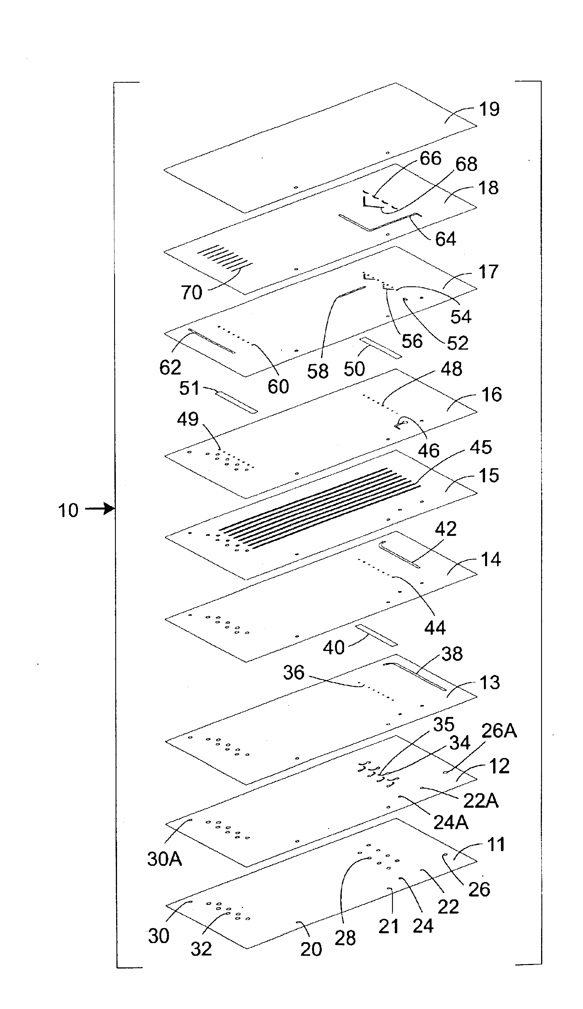
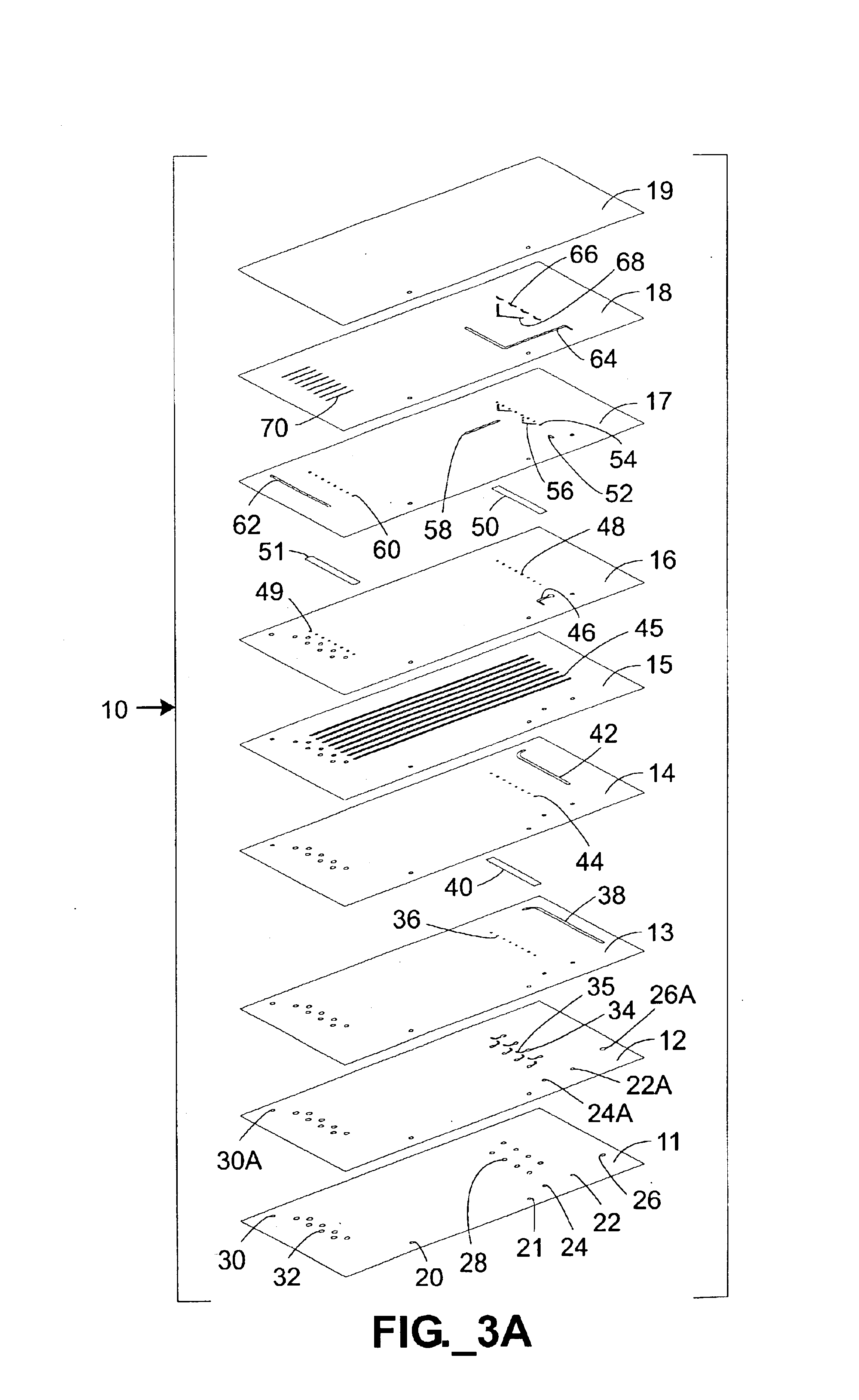
The term “microfluidic” as used herein refers to structures or devices through which one or more fluids are capable of being passed or directed and having at least one dimension less than about 500 microns.

The term “stencil” as used herein refers to a material layer or sheet that is preferably substantially planar through which one or more variously shaped and oriented portions have been cut or otherwise removed through the entire thickness of the layer, and that permits substantial fluid movement within the layer (e.g., in the form of channels or chambers, as opposed to simple through-holes for transmitting fluid through one layer to another layer). The outlines of the cut or otherwise removed portions form the lateral boundaries of microstructures that are formed when a stencil is sandwiched between other layers such...


PUM


Abstract

A splitter for multi-layer microfluidic devices is provided. The splitter includes multiple forked channels defined in two or more device layers. The forked channels communicate fluidically at overlap regions. The overlap regions, in combination with symmetrical channel geometries balance the fluidic impedance in the system and promote even splitting.

Description

FIELD OF THE INVENTIONThe present invention relates to the controlled splitting of fluid volumes in microfluidic conduits.BACKGROUND OF THE INVENTIONThere has been a growing interest in the application of microfluidic systems to a variety of technical areas, including such diverse fields as biochemical analysis, medical diagnostics, chemical synthesis, and environmental monitoring. For example, use of microfluidic systems for acquiring chemical and biological information presents certain advantages. In particular, microfluidic systems permit complicated processes to be carried out using very small volumes of fluid. In addition to minimizing sample volume, microfluidic systems increase the response time of reactions and reduce reagent consumption. Furthermore, when conducted in microfluidic volumes, a large number of complicated biochemical reactions and / or processes may be carried out in a small area, such as in a single integrated device. Examples of desirable applications for micr...

Claims


Application Information

Patent Timeline
IPC IPC(8): B01L3/00B01F13/00B01F5/04G01N30/00G01N30/10G01N30/60
CPCB01F5/0471B01F13/0059B01F15/0264G01N30/10B01L3/502746B01L3/502707B01L3/50273B01L3/502738G01N30/6095B01L2200/025B01L2300/0816B01L2300/0864B01L2300/0887Y10T137/2224B01F25/314B01F33/30B01F35/7182
Inventor KARP, CHRISTOPH D.HIGHTOWER, ADRIAN
Owner AGILENT TECH INC
Why Eureka
Try Eureka