Microelectromechanical RF and microwave frequency power regulator

a technology of microelectromechanical and power regulator, which is applied in the direction of relays, line-transmission details, waveguides, etc., can solve problems such as unusable signals being diverted

Inactive Publication Date: 2005-01-25
HRL LAB
View PDF10 Cites 105 Cited by
  • Summary
  • Abstract
  • Description
  • Claims
  • Application Information

AI Technical Summary

Problems solved by technology

In operation, when an undesirable signal is present on the transmission line, the resultant force created causes the conductive strip to flex toward, and physically co

Method used


Image

  • Microelectromechanical RF and microwave frequency power regulator
  • Microelectromechanical RF and microwave frequency power regulator
  • Microelectromechanical RF and microwave frequency power regulator

Examples


Embodiment Construction

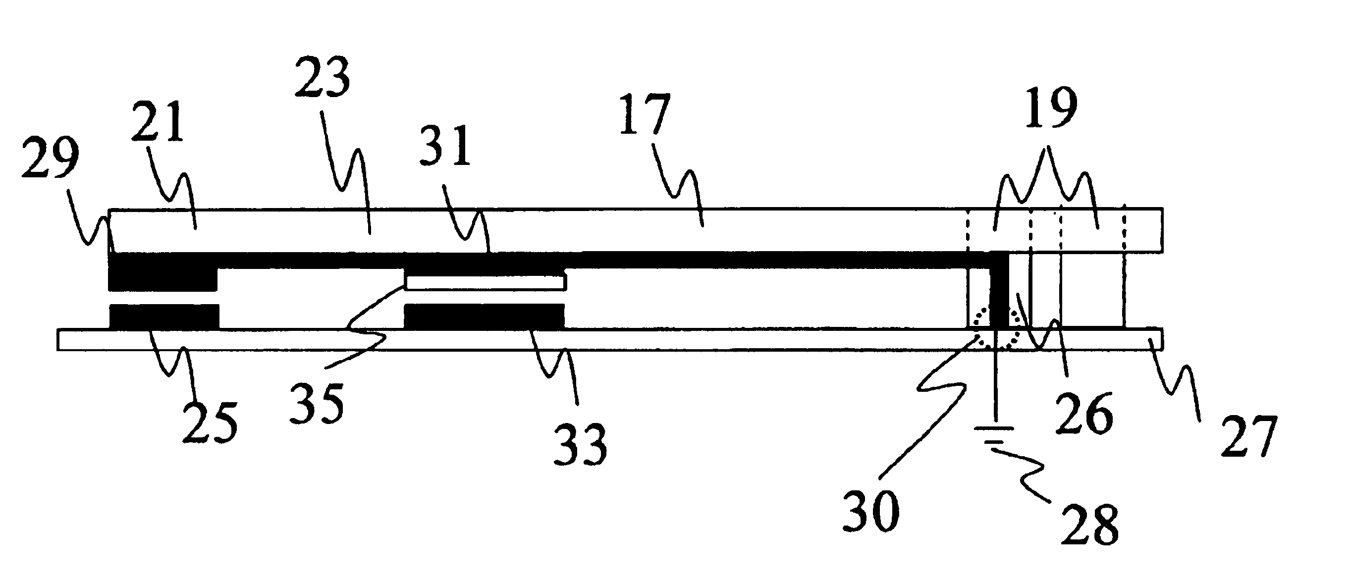
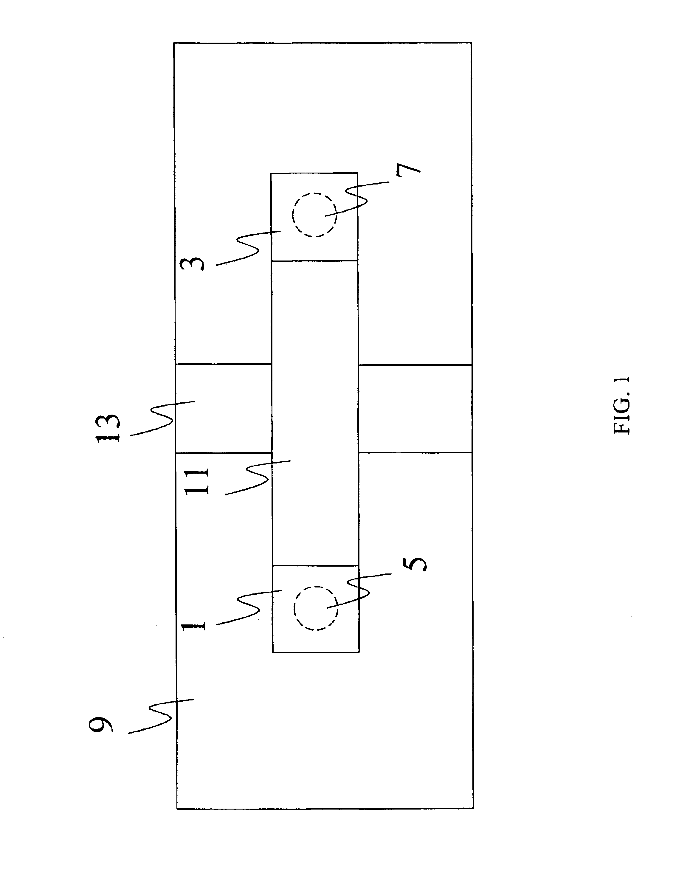
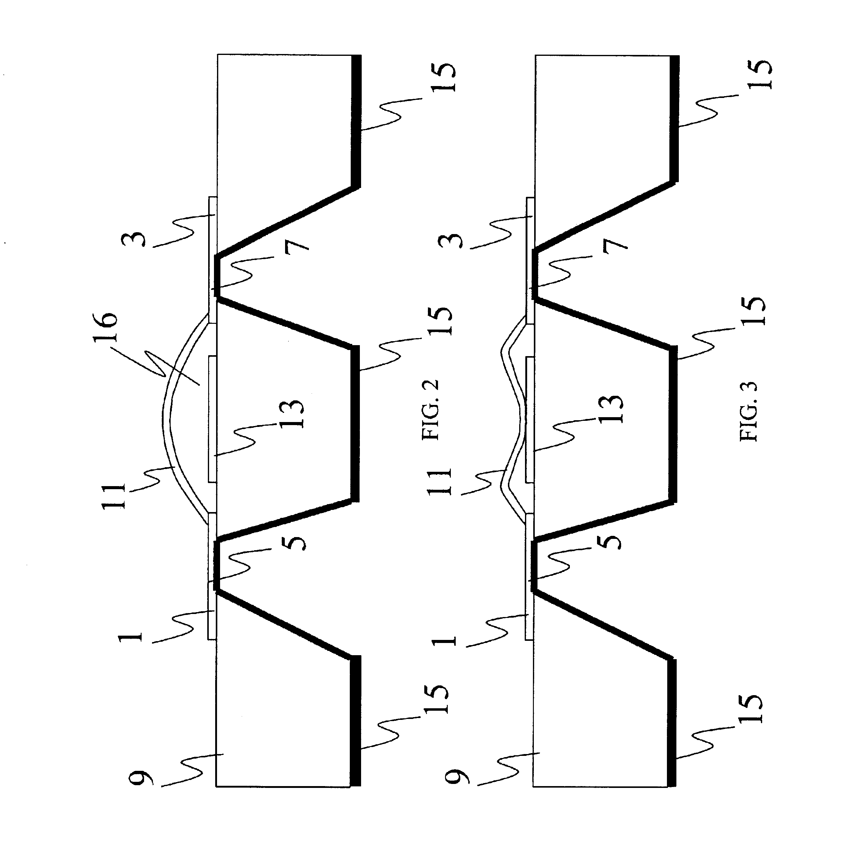
The power regulator of the present invention is useful to regulate power in microwave and millimeter wave circuits, and may be tailored to a variety of applications. The proposed power regulator has been reduced to practice in the context of two specific applications, a power limiter and an electrostatic discharge (ESD) protection unit. In both applications, the device has been utilized in both a flexible cantilever and as a bridge, as described in greater detail in the paragraphs that follow. This description will first detail the cantilever and bridge as examples of aspects of the present invention and will then proceed to detail specific applications of the present invention. These examples of aspects are presented for illustration of this invention, and are not to be considered limitations to its scope.

The present invention relates to power regulators such as power limiters and ESD protection units, as well as to apparatus incorporating them therein. The following description is...


PUM


Abstract

Microelectromechanical RF and microwave frequency power limiter and electrostatic protection devices for use in high-speed circuits are presented. The devices utilize an airbridge or a cantilever arm including a contact pad positioned operatively adjacent to an electrically conductive and substantially planar transmission line. When the power level in the transmission line exceeds a particular threshold, the airbridge or cantilever arm yields due to force between the contact pad and the transmission line, directing undesired power away from active devices. This characteristic can either serve as a method by which to limit the amount of power passing through the transmission line to a determined value or as a method by which to protect devices along the transmission line from damage due to large electrostatic bursts.

Description

TECHNICAL FIELDThe present invention discloses an effective technique to provide overload and electrostatic discharge (ESD) protection to microwave / millimeter wave monolithic integrated circuits (MMICs) including low noise amplifiers (LNAs) using a microelectromechanical (MEM) device.BACKGROUND OF THE INVENTIONIn the construction of MMICs, power regulation and, more specifically, power limiting and ESD protection are desirable to prevent device bum-out from high incident RF power.PIN diodes are typically used as power limiters, but these diodes are lossy (˜1.0 dB) at millimeter wave frequencies. Not only does the loss due to an input power limiter reduce the input signal level and thus the required amplification to reach a specified output level, but also reduces the signal-to-noise ratio by increasing the system's noise figure. Any loss due to a power limiter adds directly to the noise figure of the amplifier. Furthermore, diodes are difficult to use, as they require impedance matc...

Claims


Application Information

Patent Timeline
IPC IPC(8): H01P3/08H01P1/10H01P1/12H01H59/00
CPCH01P3/084H01P1/127H01H59/0009
Inventor LANEY, DAVIDMATLOUBIAN, MEHRANLARSON, LAWRENCE
Owner HRL LAB
Why Eureka
Try Eureka