
Integrated system for quickly and accurately imaging and modeling three-dimensional objects

a three-dimensional object, fast and accurate technology, applied in the direction of distance measurement, instruments, using reradiation, etc., can solve the problems of laborious and time-consuming process, low accuracy, low accuracy, etc., and achieve the effect of reducing labor intensity, time-consuming, and time-consuming

Inactive Publication Date: 2005-01-25
LEICA GEOSYSTEMS AG
View PDF30 Cites 170 Cited by
  • Summary
  • Abstract
  • Description
  • Claims
  • Application Information

AI Technical Summary

Benefits of technology

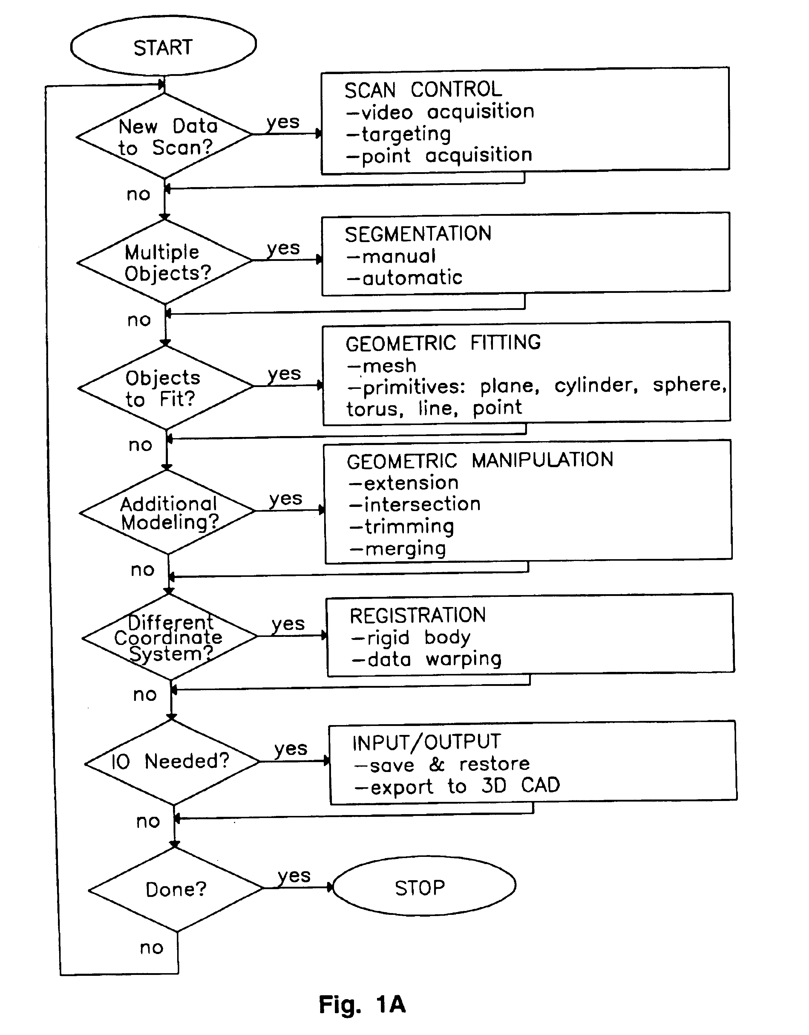
The subject invention further includes a method for modeling a three-dimensional scene, comprising: generating a plurality of points that each represent a point on a surface of the scene; determining a best fit of a cylinder for a group of the points using surface normal estimates and global error minimization.
The subject invention further includes a method for modeling a three-dimensional scene, comprising: generating a plurality of points that each represent a point on a surface of the scene; determining a best fit of a cylinder for a group of the points using a quadric surface fit and global error minimization.
The subject invention further includes a method for modeling a three-dimensional scene, comprising: generating a plurality of points that each represent a point on a surface of the scene; determining a best fit of a sphere for a group of the points using a quadric surface fit and global error minimization.
The subject invention further includes a method of warping, comprising: selecting one or more models represented by a plurality of point clouds and geometric primitives; specifying constraints on the locations of any number of points or geometric primitives; creating an artificial volume that surrounds the points and geometric primitives in each view and assigning mechanical material characteristics to the surrounding volume; computing a minimum energy configuration for the material in the surrounding volume in which the points or geometric primitives are embedded such that the configuration satisfies all applied constraints; and displacing the points and primitives in accordance with the computed minimum energy configuration of the surrounding volume of material. In the latter method, the constraints can be specified to eliminate closure errors.

Problems solved by technology

Mapping the geometry (shape, dimensions and location) and other attributes (e.g., color, texture and reflectance intensity) of complex real objects (whether small components such as small mechanical parts or large objects such as buildings and sites) has conventionally been a tedious and time consuming process.
Recently innovations have endeavored to simplify this process, but all have fallen short of achieving full integration, automation, precision, speed and range.
This process is labor intensive, time consuming, and error prone.
In addition, using traditional surveying methods, the number of points which can actually be measured is very limited, due to the high cost of acquiring each point in terms of time and effort.
Unfortunately, the plot is of little practical use since it does not indicate the object geometry.
Moreover, because of the requirement for retro reflectors which must be manually placed, and because of the relatively long time per reading required by the laser range finder, the gathering of sufficient points to describe most objects is very labor intensive, time consuming and error prone.

Method used


Image

  • Integrated system for quickly and accurately imaging and modeling three-dimensional objects
  • Integrated system for quickly and accurately imaging and modeling three-dimensional objects
  • Integrated system for quickly and accurately imaging and modeling three-dimensional objects

Examples


first embodiment

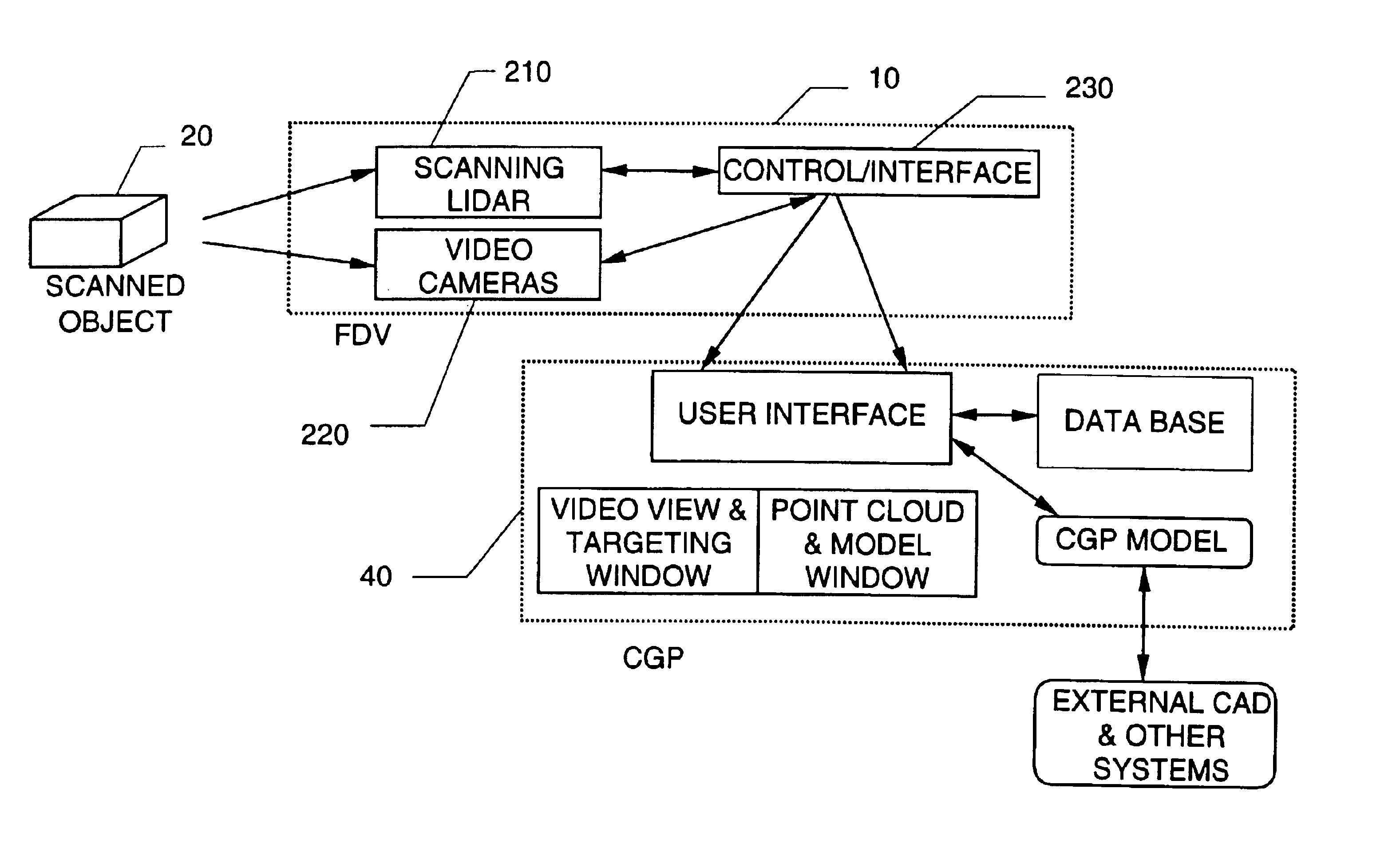
High accuracy and repeatability electronic encoders read the rotational angles of the orthogonal mirrors, and the readings of the mirror rotation angles are precisely timed to coincide with the range reading. Preferably, the system is Class II FDA eye safe. A first embodiment has ±6 mm spatial accuracy over a range of ±50 m. In another embodiment, autofocus capability and 5-6 picosecond electronics are included, which extends the system's range accuracy to ±1 mm and ±1 mm spatial accuracy over ±50 m. The range (and accuracy) of the system can be significantly influenced by the choice of eye safety classification selected, but these limitations are not inherent limitations of the invention itself

The following is a description of the key components of preferred embodiment of the FDV 10. A block diagram of the optical transceiver 502 of the FDV 10 is shown in FIG. 6. The optical transceiver 502 transmits an optical pulse to a spot on object 20, and receives a reflected optical pulse fr...


PUM


Abstract

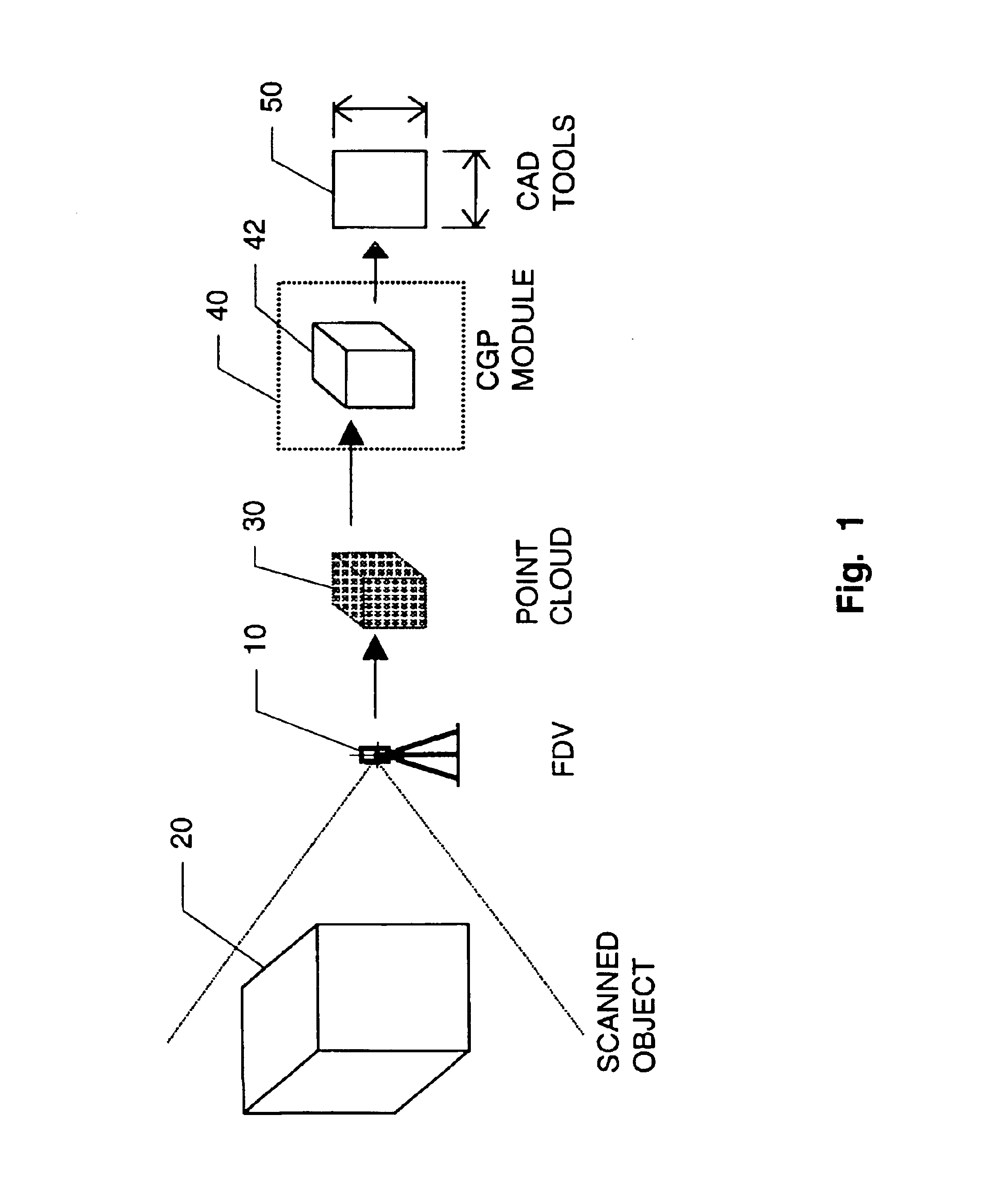
An integrated system generates a model of a three-dimensional object. A scanning laser device scans the three-dimensional object and generates a point cloud. The points of the point cloud each indicate a location of a corresponding point on a surface of the object. A first model is generated, responsive to the point cloud, that generates a first model representing constituent geometric shapes of the object. A data file is generated, responsive to the first model, that can be inputted to a computer-aided design system.

Description

TECHNICAL FIELDThe present invention relates generally to systems that document the geometry and other attributes of objects in three dimensions and, specifically, to a system that employs a scanning lidar (range finding laser) to quickly and accurately sense the position in three-dimensional space of selected points on the surface of an object to generate a point cloud which represents the sensed positions of the selected points; that recognizes geometric shapes represented by groups of points in the point cloud, and that generates a model that represents these geometric shapes. The model may be transformed into a further model usable by computer-aided design (CAD) tools, including conventional CAD tools.BACKGROUNDMapping the geometry (shape, dimensions and location) and other attributes (e.g., color, texture and reflectance intensity) of complex real objects (whether small components such as small mechanical parts or large objects such as buildings and sites) has conventionally be...

Claims


Application Information

Patent Timeline
IPC IPC(8): G01B11/24G01B11/00G01C11/00G01S17/89G01S17/00G01S7/481G01C15/00G06F17/50G06T1/00
CPCG01B11/002G01B11/24G01C11/00G01S17/89G01S7/4817G01C15/002G01S7/4818
Inventor KACYRA, BEN K.DIMSDALE, JERRYKUNG, JONATHAN APOLLO
Owner LEICA GEOSYSTEMS AG
Learn More