Optical recording medium using scattering bodies to enhance modulation

a scattering body and optical recording technology, applied in the field of optical recording mediums, can solve the problems of insufficient modulation degree, achieve the effect of efficiently enhancing the scattering effect of near-field light, generating near-field light, and being convenient to arrang

Inactive Publication Date: 2005-01-25
PIONEER CORP
View PDF10 Cites 38 Cited by
  • Summary
  • Abstract
  • Description
  • Claims
  • Application Information

AI Technical Summary

Benefits of technology

The patent describes a device that enhances the scattering effect of near-field light for recording and reading data on a recording layer. The device includes a scattering body holding layer that can hold the scattering bodies and is positioned close to the recording layer. The scattering bodies can be embedded in the recording layer or provided in a gap layer between the recording layer and the readout layer. The device improves the efficiency of the scattering effect and enhances the recording and reading of data.

Problems solved by technology

The technical problem addressed in this patent text is the insufficient degree of modulation in a super-RENS disk, which makes it difficult to commercialize the technology as an optical disk.

Method used


Image

  • Optical recording medium using scattering bodies to enhance modulation
  • Optical recording medium using scattering bodies to enhance modulation
  • Optical recording medium using scattering bodies to enhance modulation

Examples


Embodiment Construction

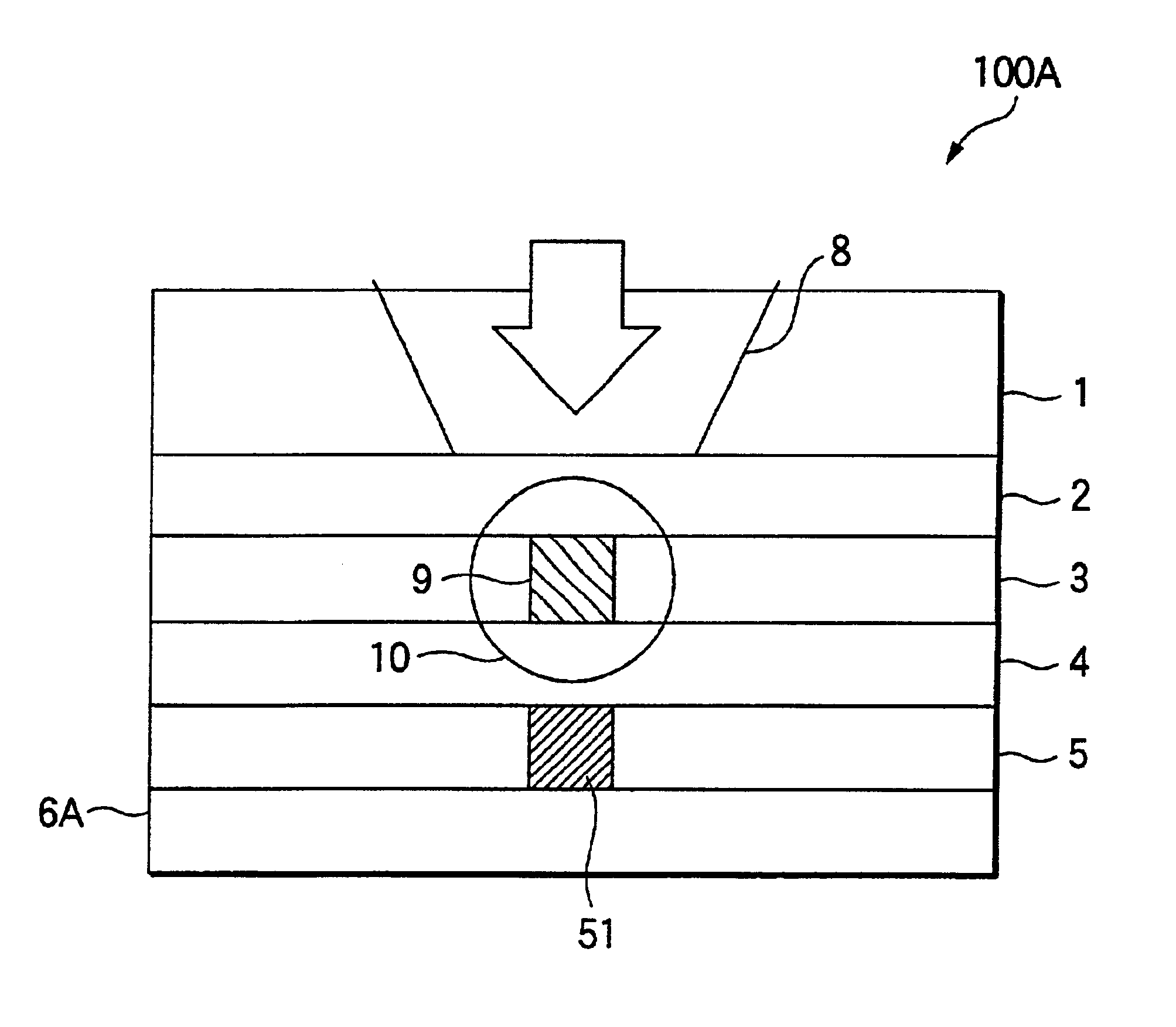
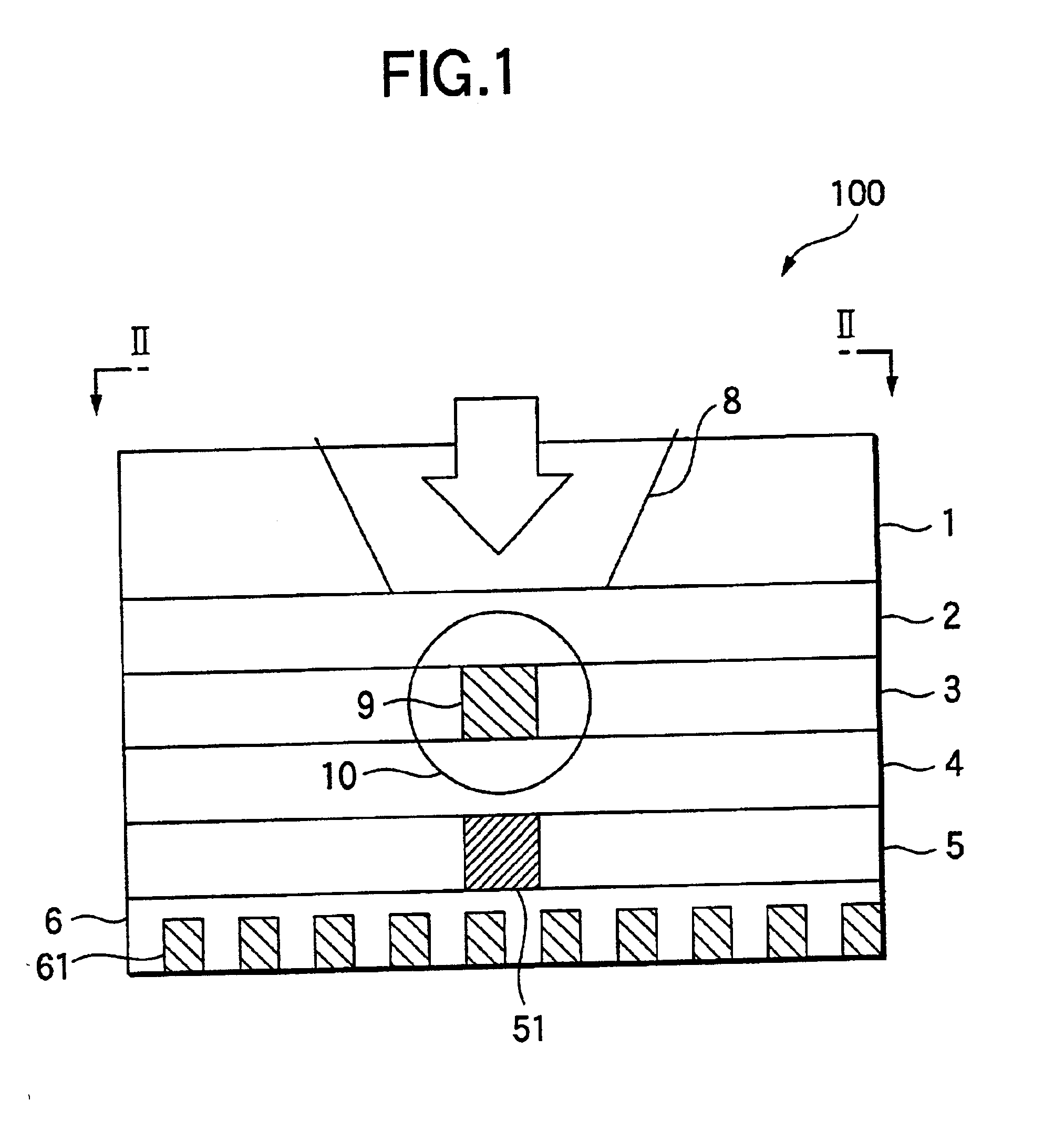
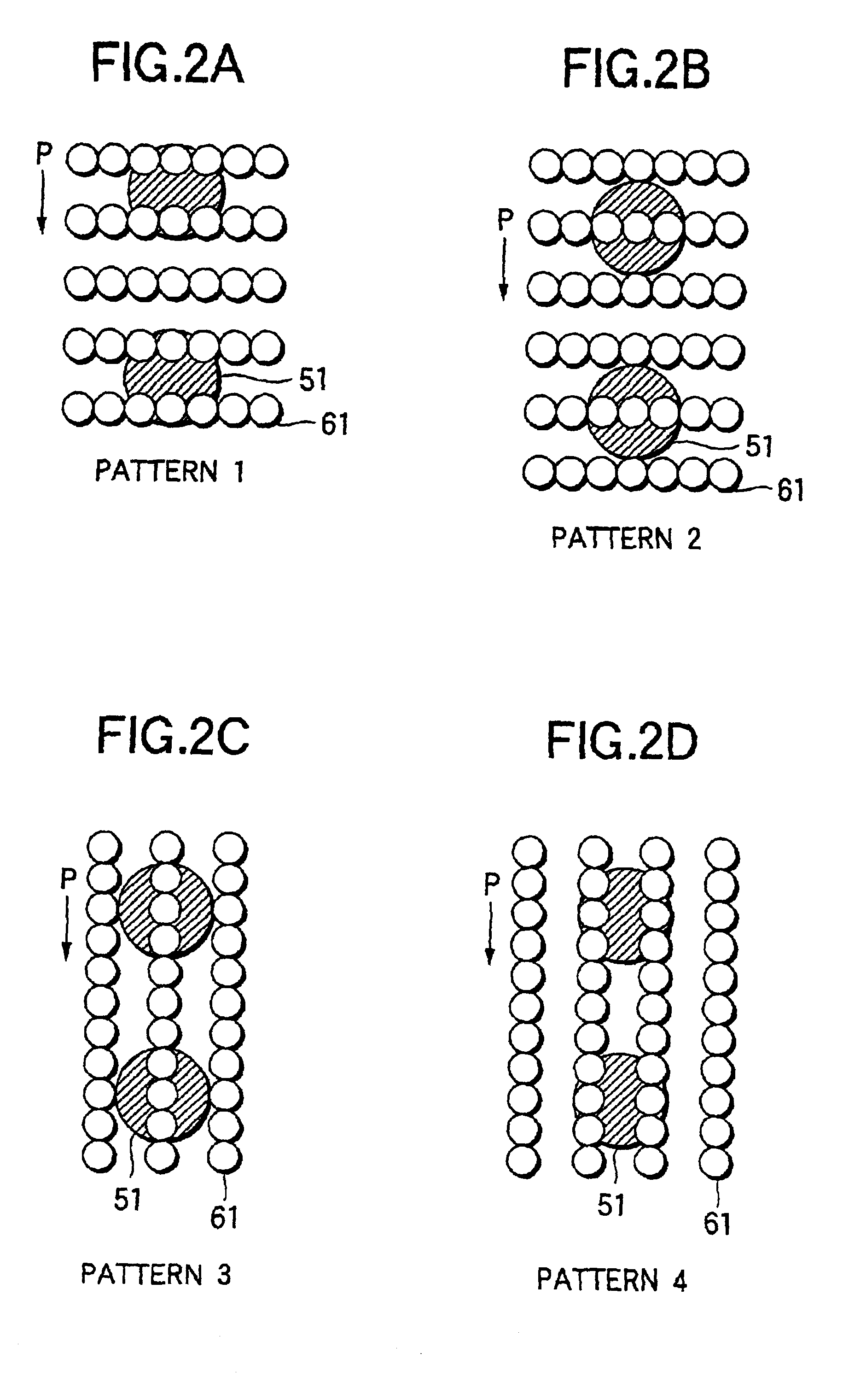
One embodiment of an optical recording medium of the invention will be described below with reference to FIGS. 1 to 4. FIG. 1 is a sectional view schematically showing the optical recording medium of the embodiment, and FIG. 2 is a diagram showing arrangement states of scattering bodies.

As shown in FIG. 1, an optical recording medium 100 of the embodiment is constructed by sequentially stacking a substrate 1 made of glass or polymeric material, a protective layer 2 made of ZnS—SiO2, a readout layer 3 made of AgOx, a gap layer 4 made of ZnS—SiO2, a recording layer 5 made of GeSbTe and a protective layer 6 made of ZnS—SiO2 from the top toward the bottom in FIG. 1. As a thickness of each the layer, for example, the gap layer 4 is 20 to 30 nm in thickness and the recording layer 5 is 30 nm in thickness and the protective layer 6 is 20 nm in thickness. The protective layer 2, the readout layer 3, the gap layer 4, the recording layer 5 and the protective layer 6 can be formed using a vapo...


PUM


Abstract

In an optical recording medium having a super-resolution layer structure using near-field light, comprising a readout layer 3 for forming a light scattering region 9 in the center portion of a laser spot, and a recording layer 5 for receiving near-field light 10 generated from the light scattering region 9 of the readout layer 3, scattering bodies 61 for increasing the generated near-field light are provided while enhancing a scattering effect of the near-field light 10 applied to a mark 51 of the recording layer 5.

Description


Claims


Application Information

Patent Timeline
Owner PIONEER CORP
Why Eureka
Try Eureka