Compressor device and control method for the same

a compressor and control method technology, applied in the direction of machines/engines, positive displacement liquid engines, lighting and heating apparatus, etc., can solve the problem of difficult to accurately control the displacement of the compressor by the pressure control valve, the operation torque of the compressor may become larger than the engine torque, and the engine may stall, etc. problem, to achieve the effect of accurately controlling the displacement of the compressor

Inactive Publication Date: 2005-02-01
DENSO CORP
View PDF17 Cites 12 Cited by
  • Summary
  • Abstract
  • Description
  • Claims
  • Application Information

AI Technical Summary

Benefits of technology

In view of the above-described problems, it is an object of the present invention to provide a compressor device which can normalize its specification between a low-power engine and a high-power engine while preventing an engine stall.
Accordingly, when the displacement of the compressor is increased in accordance with the thermal load of the refrigerant cycle system, the upper limit of the current value or the lower limit thereof can be restricted, thereby restricting the displacement of the compressor to be lower than its maximum displacement. Therefore, operation torque of the compressor can be reduced, thereby preventing engine stall at low output such as in a case where the rotational speed of the vehicle engine is lower that the predetermined rotational speed.
Preferably, the upper limit of the current value is increased from the maximum first predetermined value to the maximum current value as the rotational speed of the vehicle engine increases from a minimum rotational speed to the first predetermined rotational speed. Similarly, the lower limit of the current value is decreased from the minimum first predetermined value to the minimum value as the rotational speed of the vehicle engine increases from the minimum rotational speed to the first predetermined rotational speed. Therefore, cooling capacity of the refrigerant cycle system can be increased while a stop of the vehicle engine can be prevented.
Further, in the present invention, a pressure control valve of the compressor is controlled based on the current value supplied to the pressure control valve and a pressure difference at least between two different positions at a discharge side of the compressor. In this case, the displacement of the compressor can be accurately controlled without being affected by a suction pressure of the compressor.

Problems solved by technology

Therefore, in a case where the compressor is driven by a low-output vehicle engine and the vehicle engine is operated with a low power (low torque) such as in idling, when the displacement of the compressor is changed to a maximum side, the operation torque of the compressor may become larger than the engine torque.
Therefore, it is difficult to accurately control the displacement of the compressor by the pressure control valve.
Further, when a compressor with a large displacement is used in a low-power engine, an engine stall may be caused.

Method used


Image

  • Compressor device and control method for the same
  • Compressor device and control method for the same
  • Compressor device and control method for the same

Examples


first embodiment

(First Embodiment)

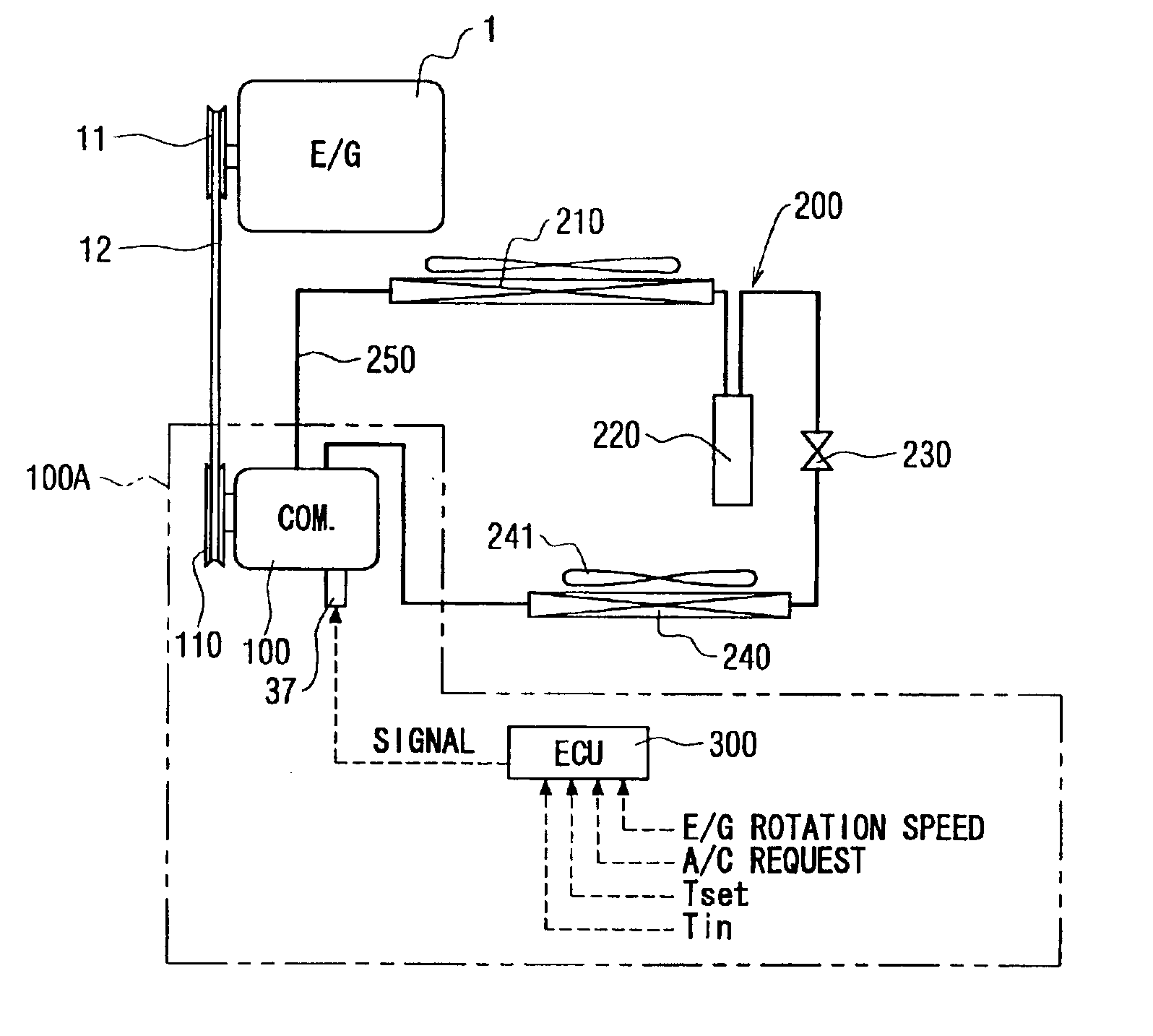
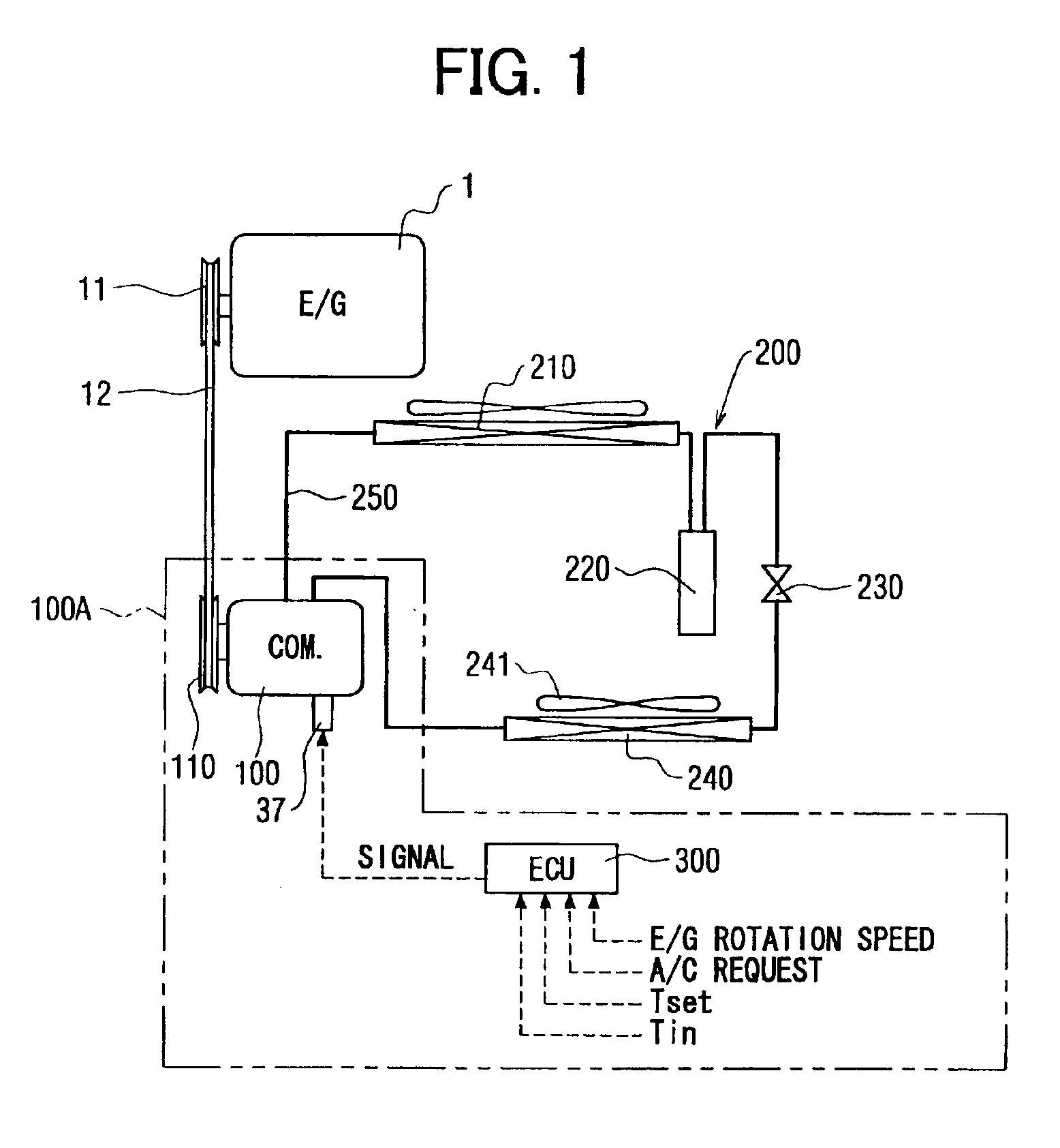
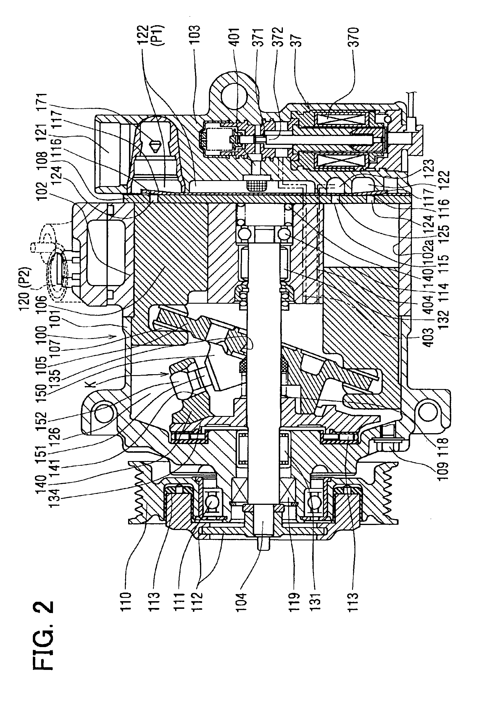
The first embodiment of the present invention will be now described with reference to FIGS. 1-6. As shown in FIG. 1, a compressor device 100A of the first embodiment includes a compressor 100 and a control unit (ECU) 300. The compressor 100 is provided in a refrigerant cycle system 200 of a vehicle. Further, the compressor 100 is operated by motive power from a vehicle engine (E / G) 1A, and compresses refrigerant in the refrigerant cycle system 200 to a high temperature and high pressure. The refrigerant cycle system 200 includes the compressor 100, a condenser 210, a receiver 220, an expansion valve 230 and an evaporator 240 which are connected by refrigerant piping 250 in this order. The condenser 210 cools and condenses refrigerant compressed by the compressor 100, and the receiver 220 separates the condensed refrigerant from the condenser 210 into gas refrigerant and liquid refrigerant. The expansion valve 230 adiabatically expands and decompresses the liquid re...

second embodiment

(Second Embodiment)

In the above-described first embodiment of the present invention, the upper limit of the current value Cv is set linearly between α1 (%) and 100 (%) in the rotational speed range of the engine between the idling speed and the predetermined rotational speed A. Similarly, in the second embodiment, the upper limit of the current value Cv is set between α1% and 100% when the rotational speed R of the engine 1 is lower than the predetermined rotational speed A. However, in the second embodiment, the upper limit of the current value Cv is stepwise changed therebetween as shown in FIG. 7, so that the control program shown in FIG. 5 is made simple. Here, in accordance with output characteristics of the engine 1, the upper limit of the current value Cv can be set at a constant value, in the rotational speed range between the idling rotational speed and the predetermined rotational speed A as shown in FIG. 8. For example, the constant value of the upper limit is α1%. Altern...

third embodiment

(Third Embodiment)

The third embodiment of the present invention will be now described with reference to FIGS. 10 and 11.

As shown in FIG. 10, in the third embodiment, a first predetermined rotational speed A similar to the above-described predetermined rotational speed of the first embodiment, and a second predetermined rotational speed B higher than the first predetermined rotational speed A are used. When the rotational speed R of the engine 1 becomes equal to or higher than the second predetermined rotational speed B, the upper limit of the current value Cv is linearly controlled between a second variable maximum value α2 (%) and maximum 100 (%). The second predetermined rotational speed B is set as a threshold for defining a rotational speed area where the rotational speed R of the engine 1 is controlled mainly based on its output power. Specifically, as shown in FIG. 11, the control operation of the control unit 300 is performed for controlling the displacement of the compressor...


PUM


Abstract

A compressor device for a refrigerant cycle includes a compressor and a control unit. The compressor is provided with a displacement changing mechanism for changing its displacement. The control unit changes a current value supplied to the displacement changing mechanism, thereby relatively changing the displacement of the compressor. In the compressor device, when a rotational speed of a vehicle engine is lower than a predetermined rotational speed, the control unit controls an upper limit of the current value between a first predetermined value and a maximum value. Accordingly, a displacement specification of the compressor device can be normalized for vehicle engines having different power outputs, while engine stall can be prevented.

Description

CROSS-REFERENCE TO RELATED APPLICATIONThis application is related to and claims priority from Japanese Patent Applications No. 2002-164360 filed on Jun. 5, 2002, and No. 2003-151391, filed on May 28, 2003, the content of which is hereby incorporated by reference.BACKGROUND OF THE INVENTION1. Field of the InventionThe present invention relates to a compressor device and a control method for controlling a compressor driven by a vehicle engine. The present invention is suitably used for a swash-plate displacement-variable compressor provided in a vehicle refrigerant cycle system.2. Description of Related ArtFor example, EP 0812987 (JP-A-9-324752) describes a compressor device for compressing refrigerant in a refrigerant cycle system. The compressor device includes a swash plate compressor, a pressure control valve and a control unit. The swash plate compressor has a swash plate that is provided in a pressure control chamber and is connected to a piston. The pressure control valve adjus...

Claims


Application Information

Patent Timeline
Patent Type & Authority Patents(United States)
IPC IPC(8): B60H1/32F04B27/18F04B27/14F25B49/02F04B49/00F04B49/06
CPCB60H1/3208F04B27/1804F25B49/022B60H2001/3266B60H2001/3275F04B2027/1813F04B2027/1827F25B2700/2104F04B2027/1854F04B2027/1895F04B2205/05F25B2400/076F04B2027/185
Inventor NOSAKA, MICHIYASU
Owner DENSO CORP
Why Eureka
Try Eureka