Shift device and switch device thereof for vehicle

Inactive Publication Date: 2005-02-01
KK TOKAI RIKA DENKI SEISAKUSHO
View PDF7 Cites 34 Cited by
  • Summary
  • Abstract
  • Description
  • Claims
  • Application Information

AI Technical Summary

Benefits of technology

Accordingly, it is an objective of the present invention to provide a shift device that reduces the proj

Problems solved by technology

A typical shift lever locking mechanism locks a shift lever at the parking position and does not permit the shift lever to be moved to another position unless the driver perfo

Method used


Image

  • Shift device and switch device thereof for vehicle
  • Shift device and switch device thereof for vehicle
  • Shift device and switch device thereof for vehicle

Examples


first embodiment

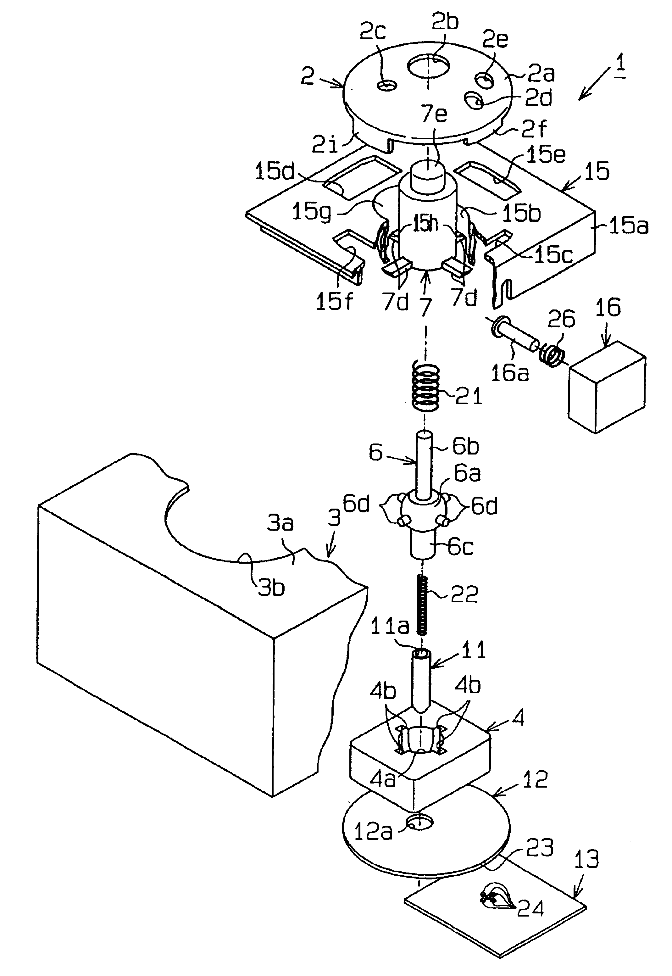
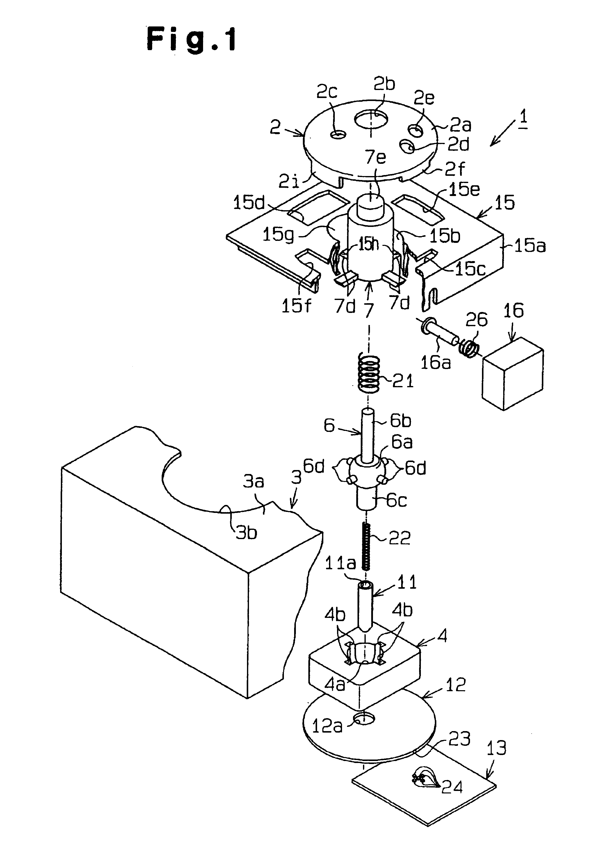
A selector device according to a first embodiment of the present invention will now be described with reference to FIGS. 1 to 6. The selector device is located on a floor console of a vehicle.

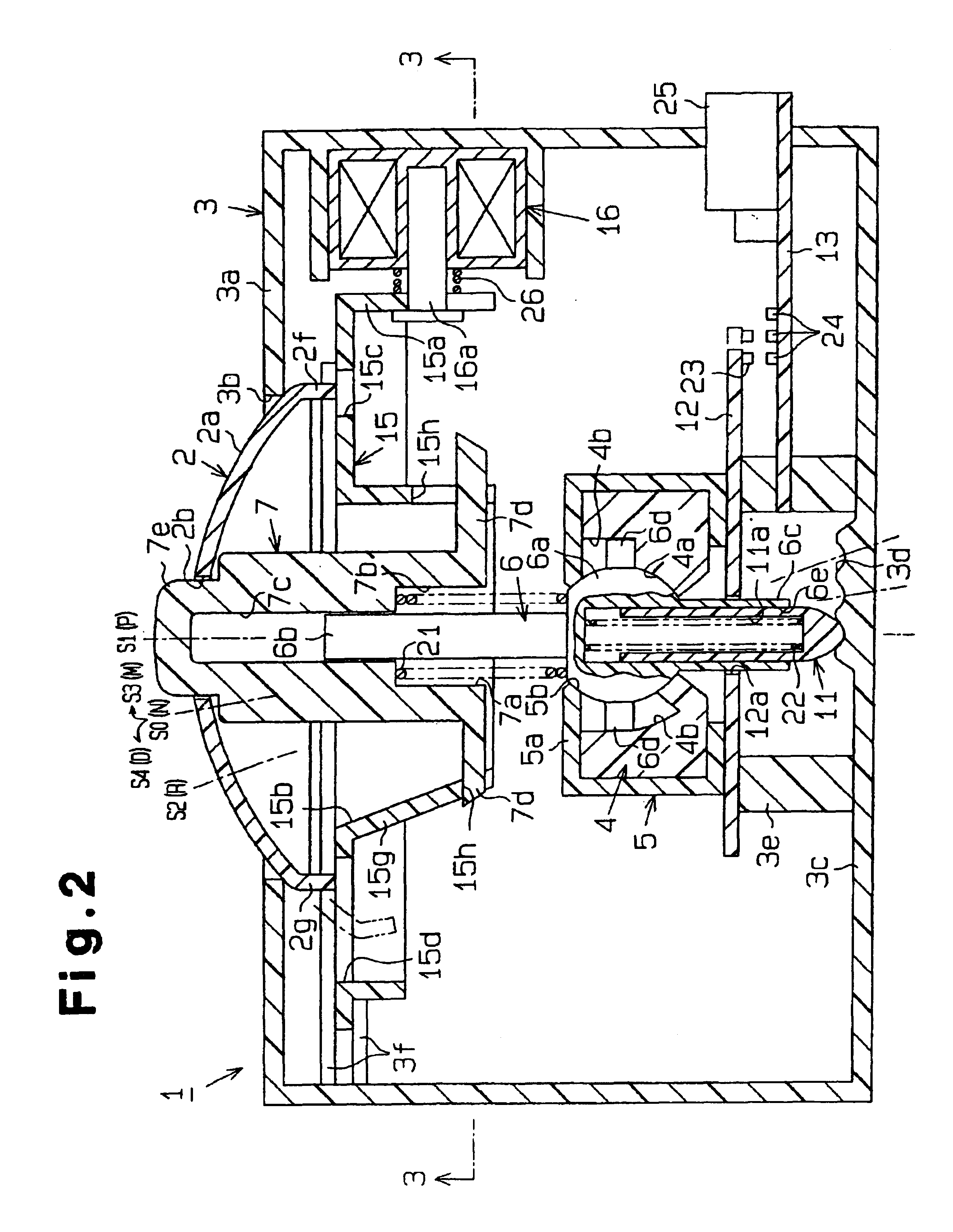
As shown in FIG. 4(d), a shift device 1 is integrally attached to a floor console F. The shift device 1 has a substantially dome-shaped semispherical knob 2, which is substantially located in the same plane as the floor console F. The semispherical knob 2 is moved in forward, rearward, leftward and rightward directions of the vehicle (crossing directions). The semispherical knob 2 is arranged such that the center position in the cross (a selected position S0, which will be described below) is inclined rearward (toward the driver). As shown in FIGS. 1 and 2, the shift device 1 has a case 3. A substantially circular hole 3b is formed in an upper wall 3a of the case 3. A part of the semispherical knob 2 projects from the case 3 so that an upper surface 2a of the knob 2 bulges into the passenger co...

second embodiment

A second embodiment of the present invention will now be described with reference to FIGS. 8 to 10.

As shown in FIG. 8, a switch device 51 of a shift switch is installed in a floor console C. The switch device 51 includes a base plate portion 52. A palm rest 53, which functions as a resting portion, projects from the base plate portion 52. The driver lays hand on the palm rest 53 while in the driving posture. At positions where fingers are placed, push buttons 55, the number of which is five in this embodiment, project from the base plate portion 52. The buttons 55 conform a handprint. When pushed, each push button 55 outputs an ON signal.

As shown in FIG. 9(a), the push button switches 55 include an R button switch 55a for the reverse state, a P button switch 55b for the parking state, an N button switch 55c for the neutral state, and a D button switch 55d for the drive state. The R button switch 55a is located at a position corresponding to the thumb. The P button switch 55b is loca...


PUM


Abstract

A shift device has an operation member for operating a vehicular automatic transmission. The operation member is formed to conform to the shapes of a hand and fingers of a driver.

Description

BACKGROUND ARTThe present invention relates to a vehicular shift device, more particularly to a shift-by-wire type shift device.In a typical automobile having an automatic transmission, the shift lever of the transmission is manipulated to change the shift position. The shift lever protrudes into the passenger compartment and uses leverage for transmitting a predetermined amount of force.A typical shift lever locking mechanism locks a shift lever at the parking position and does not permit the shift lever to be moved to another position unless the driver performs another operation such as pressing of the brake pedal. For example, Japanese Laid-Open Patent Publication No. 10-59132 discloses such a shift lever device. The shift lever of the device is reciprocated in a linear shift gate. One end of the gate is the parking position. When the shift lever is located at the parking position, an engaging projection formed on the shift lever engages with a lock pin, which is driven by an act...

Claims


Application Information

Patent Timeline
IPC IPC(8): F16H59/08F16H59/02B60K20/06B60K20/04F16H59/10
CPCF16H59/0278F16H59/08B60K20/04B60K20/06F16H59/105Y10T74/2003F16H61/24Y10T74/20159Y10T74/20085Y10T74/20128Y10T74/2014F16H59/12
Inventor HAYASHI, MASAKIKUNIMATSU, YOSHIMASASYAMOTO, NORIYASU
Owner KK TOKAI RIKA DENKI SEISAKUSHO
Why Eureka
Try Eureka