Resolver

a technology of a resolver and a radial projection, which is applied in the direction of magnets, instruments, magnets, etc., can solve the problems of difficult to arrange the jig and breakage of wires, and achieve the effect of reducing the size of the resolver, reducing the amount of radial projection of the terminal holding part, and simplifying the operation

Active Publication Date: 2015-11-26
MINEBEAMITSUMI INC
View PDF20 Cites 6 Cited by
  • Summary
  • Abstract
  • Description
  • Claims
  • Application Information

AI Technical Summary

Benefits of technology

[0010]The fixing means can have a pin that is arranged on the terminal holding part, and can have a hole that is formed in the stator core and to which the pin engages. The pin is press-fitted in the hole when the terminal holding part is arranged at the secondary position, so that the terminal holding part is fixed at the secondary position. In this aspect, since the pin is press-fitted into the hole by moving the terminal holding part to the secondary position, there are fewer processes and the operation can be simplified. In addition, since the pin is fixed to the stator core, the terminal holding part can be strongly fixed.
[0011]The terminal holding part can be arranged on the insulator that is movable along the radial direction of the stator core. Since the plurality of salient poles project toward the outside direction of the radial direction of the stator core in the outer rotor type resolver, the terminal holding part is arranged inside of the stator core. On the other hand, since the a plurality of salient poles project toward the inside direction of the radial direction of the stator core in the inner rotor type resolver, the terminal holding part is arranged at the outer circumferential side of the stator core. In this aspect, since the lead wire becomes slack by moving the terminal holding part closer to the stator core side, the amount of projection of the terminal holding part in the radial direction can be reduced, thereby reducing the size of the resolver.

Problems solved by technology

In such a structure, if the lead wire from the stator to the terminal pin is under tension, the lead wire may break due to temperature changes or the like.
However, it is difficult to arrange the jig, in a case in which there is no room at outside like the outer rotor type resolver having rotor at outside of the stator, or in a case in which a distance between the end of the wound wire and the terminal pin cannot be maintained even in the inner type resolver disclosed in the above publication.

Method used


Image

  • Resolver
  • Resolver
  • Resolver

Examples


second embodiment

4. Second Embodiment

[0044]The second embodiment of the present invention is explained with reference to FIGS. 7 to 10.

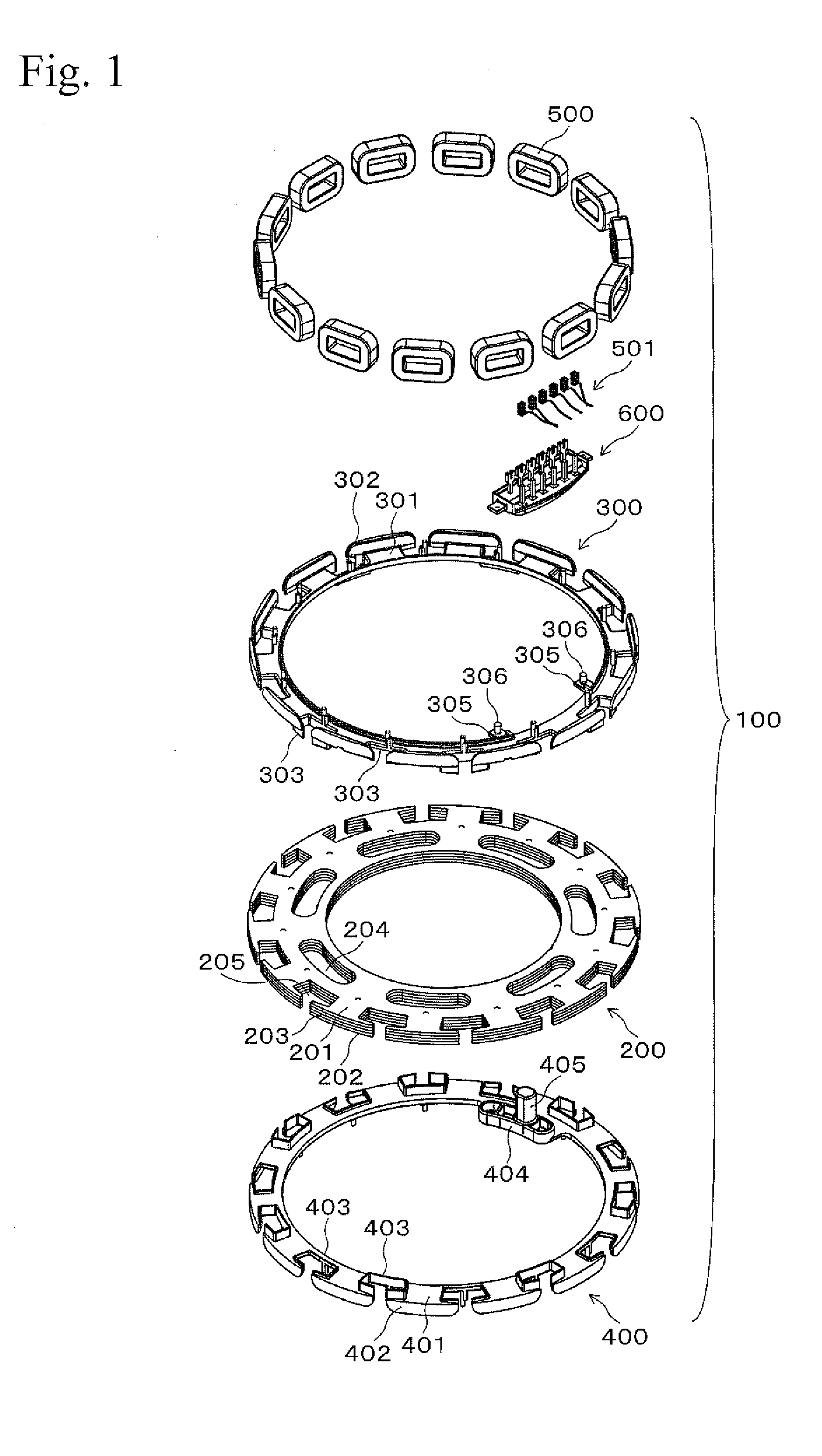
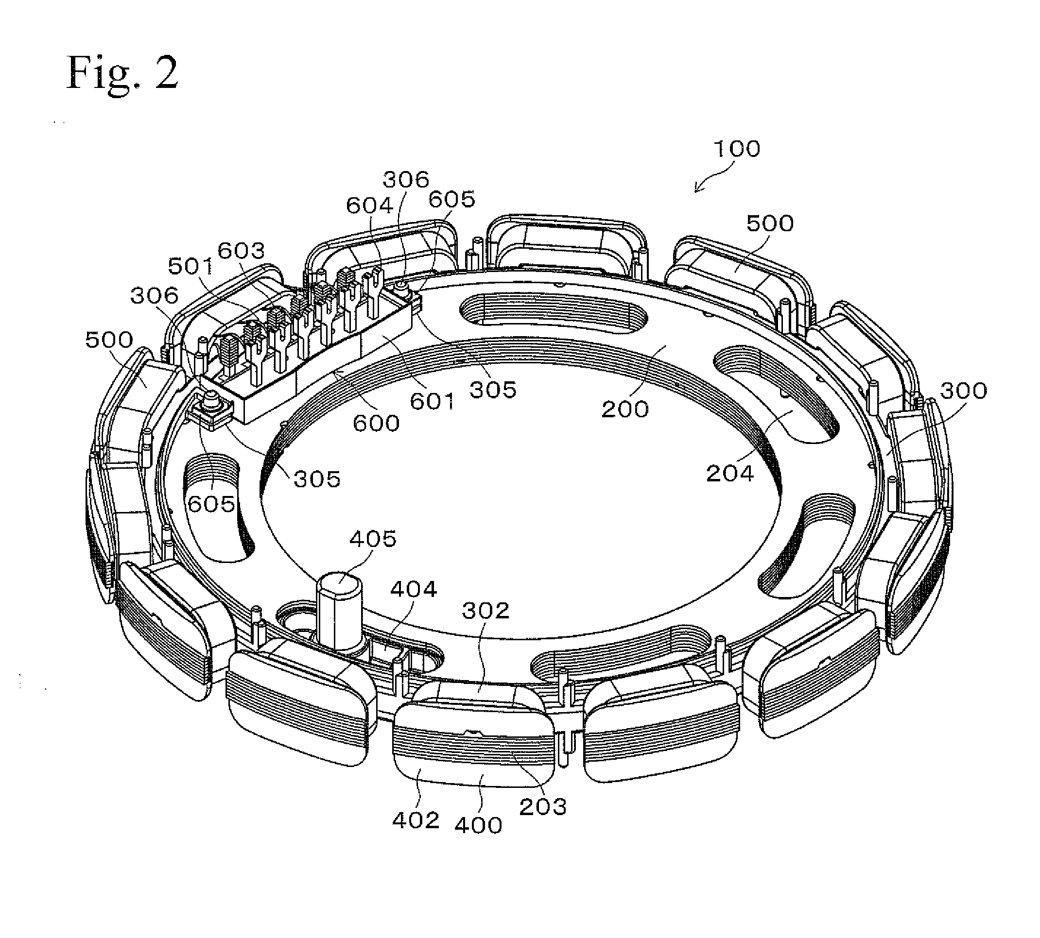
[0045]FIG. 7 is an exploded perspective view showing a condition in which a stator 100A of a VR type resolver of the second embodiment is disassembled along the axial direction. The stator 100A has an approximately circular shape. At the inside of the stator 100A, a rotor that is constructed of a soft magnetic material is held in a condition so as to be rotatable with respect to the stator 100A. It should be noted that the figure and the explanation of the rotor structure is omitted since it is as same as that of an ordinary VR type resolver.

[0046]The stator 100A includes a stator core 200A. The stator core 200A has a structure in which a soft-magnetic material (silicon steel plate, for example) is processed by press-cutting into approximately circular shapes, and the multiple plates are stacked along the axial direction, as shown in FIG. 7. In the stator core 200A, ...


PUM

PropertyMeasurementUnit
tensionaaaaaaaaaa
thicknessaaaaaaaaaa
temperatureaaaaaaaaaa

Abstract

A resolver has a lead wire that can be slack even in a structure in which it is impossible to maintain the distance between an end of wound wire and a terminal pin without using a special jig. A lead wire of a stator coil 500 is entwined on a plurality of terminal pins 603 in a slack condition, and the entwined parts are fixed by soldering or welding. Terminal base 600 is then moved to a stator core 200 side, and the lead wire is made slack by contacting the lower surface of a terminal base body 601 to the upper surface of the stator core 200. Next, end part of the pins 306 of a primary insulator 300 are melted so as to fix the terminal base 600.

Description

TECHNICAL FIELD[0001]The present invention relates to resolvers, and in particular, relates to a technique in which a lead wire extending from an end of a wound wire of a stator coil is slack after the lead wire is connected to a terminal pin, in a VR type resolver (variable reluctance type resolver) for example.BACKGROUND ART[0002]A VR type resolver that is used for detection of rotation position or the like has a structure in which a plurality of salient poles for magnetic poles are projected from a circular stator core in an outer or inner direction of the radial direction, and a rotor that is constructed of magnetic material is arranged inside or outside of the stator having a wound wire wound around the salient poles thereof.[0003]Here, a terminal holding part having a plurality of terminal pins is arranged in the stator, and a lead wire extending from an end of a wound wire wound around the plurality of salient poles of the stator, is entwined at the plurality of terminal pins...

Claims


Application Information

Patent Timeline
Patent Type & Authority Applications(United States)
IPC IPC(8): G01D5/20H01F41/10H01F41/06
CPCG01D5/2046Y10T29/49073H01F41/10H01F41/0616H02K3/325H02K3/522
Inventor MIYAO, KAZUKI
Owner MINEBEAMITSUMI INC
Why Eureka
Try Eureka