Signal receiver having light guide for guiding light transmitted from remote control

a technology of remote control and signal receiver, which is applied in the field of signal receiver for remote control system, can solve the problems of inability to prevent foreign substances from entering the range within which a light can be received, the receiver cannot mount the photodetector directly on the circuit board, and the range of light can be extremely limited, so as to achieve efficient concentration and reduce the amount of projection. , the effect of enhancing light utilization

Inactive Publication Date: 2007-07-31
FUNAI ELECTRIC CO LTD
View PDF22 Cites 1 Cited by
  • Summary
  • Abstract
  • Description
  • Claims
  • Application Information

AI Technical Summary

Benefits of technology

[0018]According to the aspect of the present invention, since the light guiding portion has a substantially circular cross section and is curved gently, a light that is passing through the inside of the light guide can be better prevented from leaking outward in the same manner as the above. The axis of the concave surface, the axis of the cross section of the light guiding portion, and the axis of the light-receptive portion of substantially dome shape (having a convex surface) are coaxial with each other. Accordingly, the overlap in a plan view between the exit end and the light-receptive portion becomes relatively large, and the concave surface of the exit end and the convex surface of the light-receptive portion are configured to be coaxial with and opposite to each other. Thus, light flux passing through the light guide can be efficiently concentrated into the light-receptive portion, whereby the light utilization is enhanced. By configuring the light guide to have a substantially circular cross section while having a concave surface at the exit end, the amount of the projection can be reduced at the edge of the exit end. Thus, the exit end and the light-receptive portion can be prevented from interfering with each other when the front panel is attached to a main body of the signal receiver. As a result, the exit end can be extended to the vicinity of the light-receptive portion, whereby the photodetector can be improved in sensitivity. The light guide is typically made of a material increased in refractive index compared to the atmosphere. By making a single layer light guide out of such a material, a light can be reflected totally by the boundary between its outer surface and the atmosphere to be guided.

Problems solved by technology

In the signal receiver disclosed in Japanese Utility Model No. 3041970, however, it is not taken into consideration to enable the light guide to change the direction of an optical signal at substantially a right angle, thereby the receiver failing to mount the photodetector directly on the circuit board.
However, the window in the receiver is configured to be open, thereby failing to prevent an invasion of foreign substances.
Such a step, however, causes the range within which a light can be received to be extremely limited due to the influence of surface reflection, thus a problem may arise in utility.
Thus, such a configuration is not suitable for a signal receiver which requires receiving optical signals emitted from various directions.
Additionally, an optical fiber is expensive due to its two-layered structure consisting essentially of a core layer and a clad layer, thereby increasing the production cost of the receiver.
Thus, the receiver is increased in production cost.
However, when the metal mold 10 for use in molding of the light guide 9 is configured to have a rectangular section as shown in FIG. 6, the shrinkage caused by cooling further lowers the light utilization.
This may cause an interference between the edge of the light guide 9 and the light-receptive portion 41 when the front panel 2 is attached to the main body of the receiver.

Method used


Image

  • Signal receiver having light guide for guiding light transmitted from remote control
  • Signal receiver having light guide for guiding light transmitted from remote control
  • Signal receiver having light guide for guiding light transmitted from remote control

Examples


Embodiment Construction

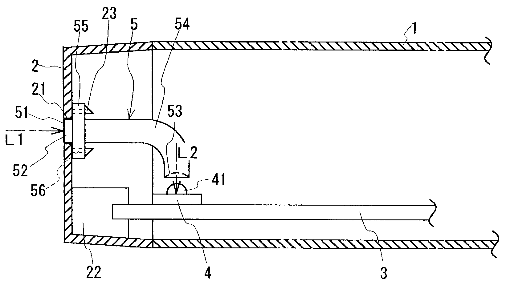
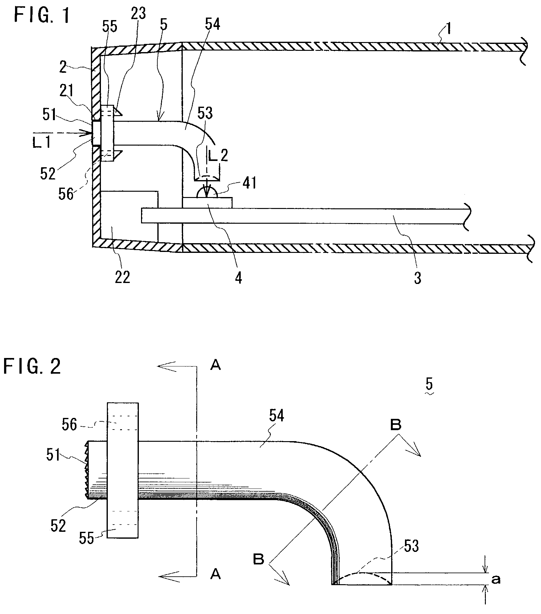
[0025]Now, a signal receiver according to an embodiment of the present invention will be described with reference to the accompanying drawings. FIG. 1 illustrates a cross sectional view of the signal receiver. The signal receiver is provided for receiving an optical signal on infrared rays or the like transmitted from a remote control and converting the optical signal into an electric signal, and it is applied to electronic machines such as a videocassette recorder. The signal receiver comprises a front panel 2 attached to the front side of an outer casing 1, a circuit board 3 disposed at substantially a right angle to the front panel 2, a photodetector 4 mounted on the circuit board 3, a light guide 5 for guiding toward the photodetector 4 an optical signal passing through a window 21 provided at the front panel 2.

[0026]The front panel 2 includes, in addition to the window 21 for receiving an optical signal, a stand 22 for holding the circuit board 3 and a couple of claws 23 for en...


PUM


Abstract

A signal receiver which receives an optical signal from a remote control includes a light guide for guiding a light passing through a front panel window toward a photodetector mounted on a circuit board. The light guide is made of a homogeneous material. A light guiding portion of the light guide extending from an entrance end to an exit end has a substantially circular cross section and is curved gently, not angularly. The exit end is configured to have a concave surface which is coaxial with the axes of both the cross section of the light guiding portion and a light-receptive portion of the photodetector. The exit end is disposed adjacent and opposite to the light-receptive portion.

Description

BACKGROUND OF THE INVENTION[0001]The present invention relates to an apparatus for receiving an optical signal transmitted from a remote control and converting the signal to an electric signal. More particularly, the present invention relates to a signal receiver for a remote control system in which a photodetector is disposed so as to have a directivity thereof substantially perpendicular to a direction in which a light enters through a front panel window.[0002]There have been conventionally provided a variety of signal receivers which comprise a light guide for guiding an optical signal passing through a window toward a photodetector mounted on a circuit board. For example, a signal receiver is known which is designed to improve the strength of the light guide and permit a light to be received at various angles by making, out of a translucent resin material, the columnar portion of the light guide integrally with ribs for strengthening it (e.g., Japanese Utility Model No. 3041970)...

Claims


Application Information

Patent Timeline
Patent Type & Authority Patents(United States)
IPC IPC(8): H04B10/06G02B6/42G02B6/44G02B6/00H01L31/0232H04B10/11H04B10/67H04N5/00H04Q9/00
CPCG02B6/00G02B6/4202
Inventor MAEDA, OSAMUMORISADA, KATSUHIRO
Owner FUNAI ELECTRIC CO LTD
Why Eureka
Try Eureka